Trapped-vortex combustor with swirlers

A swirler and combustion chamber technology, applied in the field of vortex combustion chambers, can solve the problems of weak strength in the recirculation zone, insufficient vortex stability, and the degree of oil-gas mixing in the concave cavity needs to be improved, so as to achieve good combustion, stable flame, and improved The effect of the degree of atomization and the degree of oil-air mixing

Inactive Publication Date: 2018-11-06
NORTHWESTERN POLYTECHNICAL UNIV
View PDF3 Cites 5 Cited by
  • Summary
  • Abstract
  • Description
  • Claims
  • Application Information

AI Technical Summary

Problems solved by technology

Conventional vortex combustors generally control the jet flow passing through the front and rear walls of the cavity to form a vortex, which makes the vortex less stable, so the formed recirculation zone is weaker and is easily affected by the mainstream air, and the oil and gas in the cavity are mixed. The degree also needs to be improved

Method used


Image

  • Trapped-vortex combustor with swirlers
  • Trapped-vortex combustor with swirlers
  • Trapped-vortex combustor with swirlers

Examples


Embodiment Construction

[0019] The present invention will be further described now in conjunction with accompanying drawing:

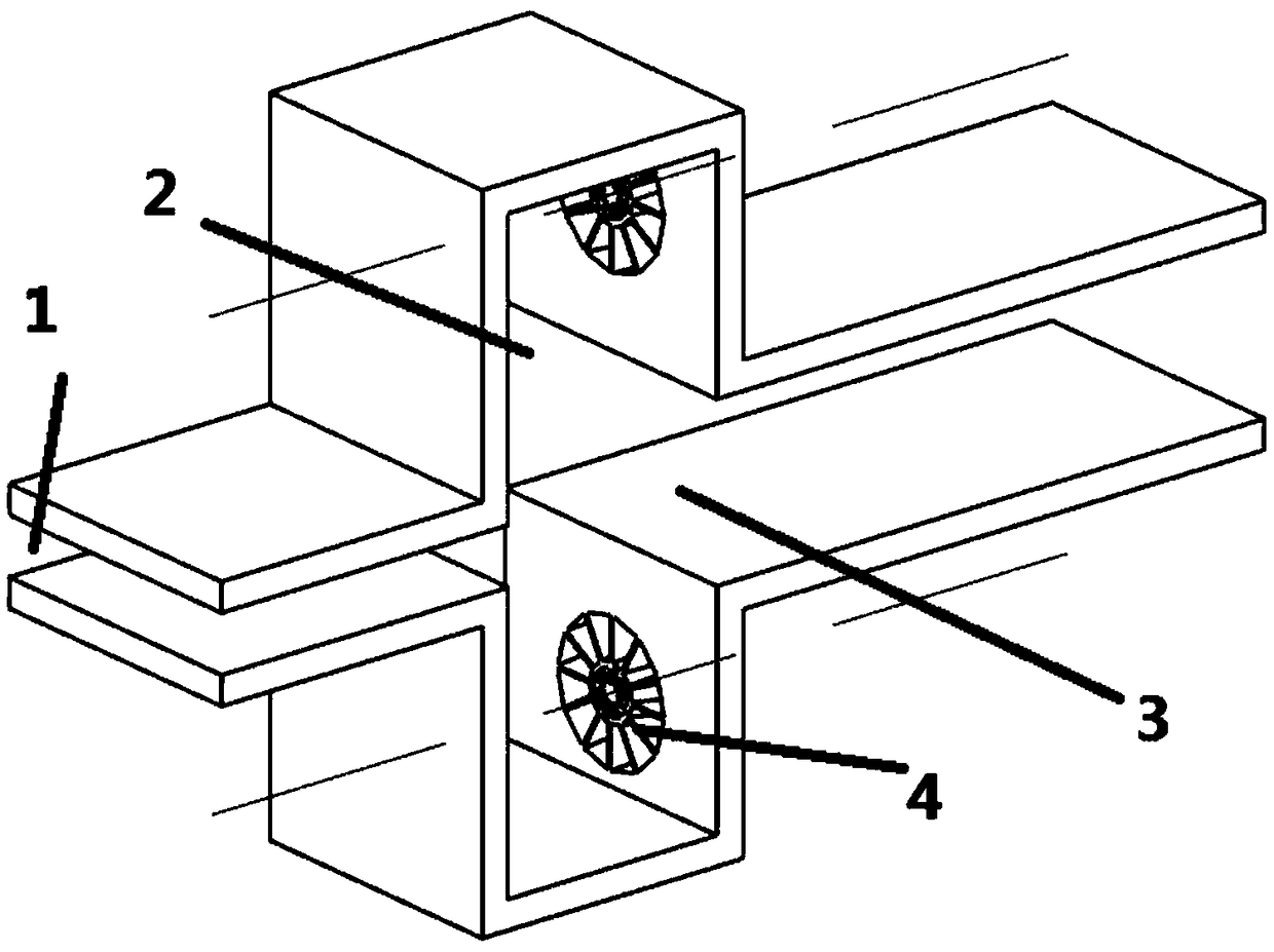
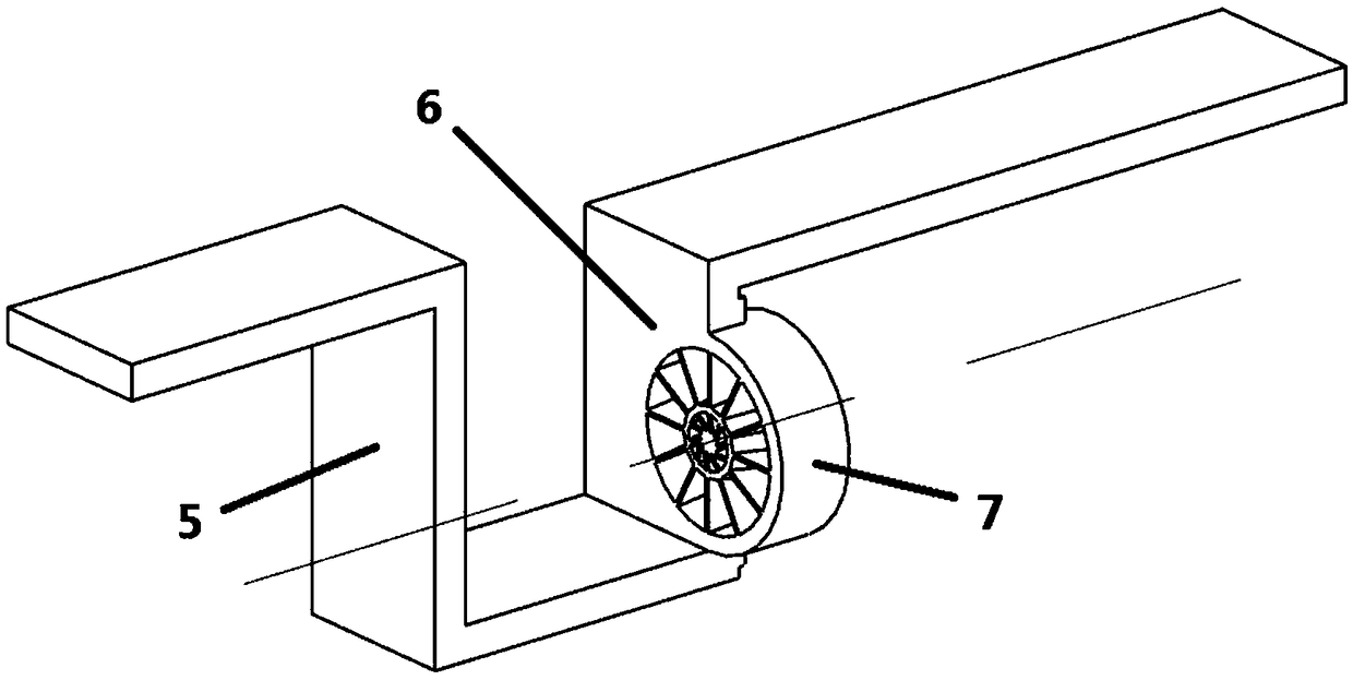
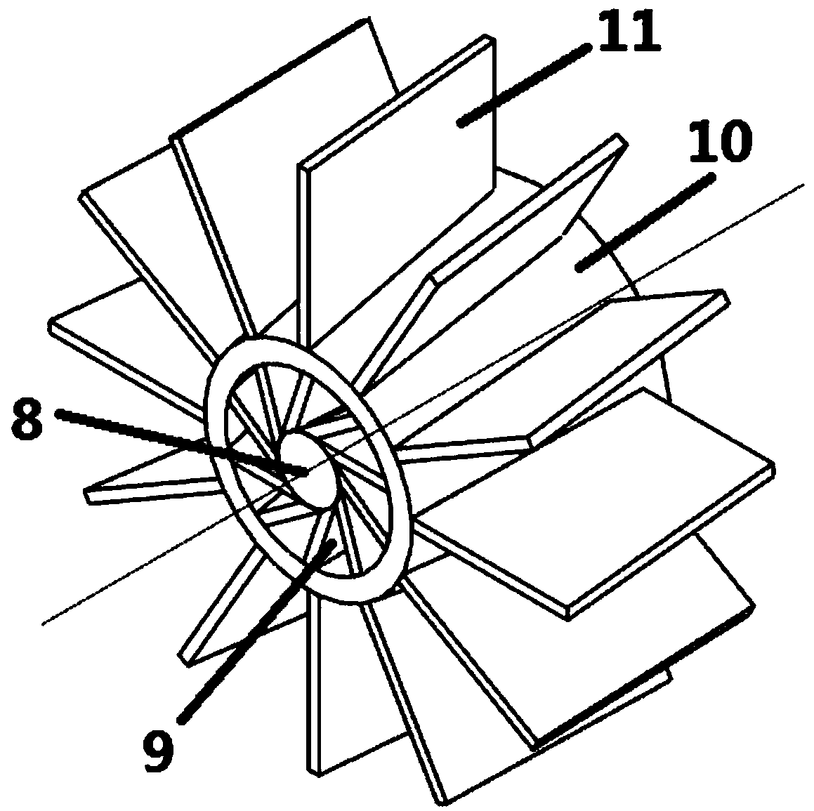
[0020] combine figure 1 , figure 2 , image 3 , the present invention arranges an axial swirler on the rear wall of the cavity of the trapped vortex combustion chamber. figure 1 It is an overall schematic diagram of a trapped vortex combustor with a swirler, figure 2 It is a partial sectional view of a trapped vortex combustor with a swirler, image 3 It is a partial schematic diagram of a trapped vortex combustor with a swirler.

[0021] Such as figure 1 As shown, oil and gas in the trapped vortex zone enter into two symmetrical concave cavities (2) respectively through two swirlers (4) distributed symmetrically with respect to the axis of the combustion chamber. Such as figure 2 As shown, the peripheral cylindrical sleeve (7) of the cyclone is connected with the rear wall (6) of the cavity. Such as image 3 As shown, since the primary cyclone blade (9) and the s...


PUM


Abstract

The invention provides a trapped-vortex combustor with swirlers. The swirlers which are matched with the combustor are arranged on the rear wall faces of concave cavities of the trapped-vortex combustor, two-stage blades of each swirler have a certain angle, after the oil gas in a trapper-vortex region passes through the swirlers, the flow state can be changed, rotational flow can be formed, and therefore flow return regions with the high strength are formed in the concave cavities, the influence of the main air flow on the flow of the concave cavities is reduced, and a stable high-temperatureheat source is provided for a main combustion region. Meanwhile, due to the fact that the two-stage blades of each swirler are opposite in rotating direction, the high shear force exists between theair flow ejected from the two-stage blades, the atomization degree of fuel oil of the trapped-vortex region and the oil and gas mixing degree can be greatly improved, and the combustion efficiency isimproved.

Description

technical field [0001] The invention belongs to the field of a vortex combustion chamber, in particular to a vortex combustion chamber with a swirler. Background technique [0002] The trapped vortex combustor is a new type of combustion organization developed since the mid-1990s. The stagnant vortex combustor adopts the concept of staged and partitioned combustion. The pre-combustion stage is composed of a concave cavity. Air is supplied into the cavity to form a vortex, and fuel is supplied at the same time. Since the vortex of the pre-combustion stage is settled in the cavity, it is called A trapped vortex combustor. The test shows that compared with the traditional combustor, the trapped vortex combustor has shown superior performance in terms of ignition, lean flameout, in-flight re-ignition and combustion efficiency. [0003] Since the trapped vortex combustor mainly uses the vortex formed by the concave cavity to generate a recirculation zone to stabilize the flame ...

Claims


Application Information

Patent Timeline
Patent Type & Authority Applications(China)
IPC IPC(8): F23R3/58
CPCF23R3/58
Inventor 张群海涵张鹏王鑫宋亚恒寇睿李承钰
Owner NORTHWESTERN POLYTECHNICAL UNIV
Why Eureka
Try Eureka