Eureka AIR delivers breakthrough ideas for toughest innovation challenges, trusted by R&D personnel around the world.

High-efficiency condensed water recovery device

A technology for recycling device and condensate water, applied in the field of water treatment, can solve the problems of inefficient energy-saving evaporation, ordinary condensate water recycling device can not self-supply water and drainage, etc., to achieve the effect of saving energy, improving practical performance and convenient operation

Inactive Publication Date: 2018-11-06
黄山市雅龙智能科技有限公司
View PDF0 Cites 4 Cited by
  • Summary
  • Abstract
  • Description
  • Claims
  • Application Information

AI Technical Summary

Problems solved by technology

[0002] With the development of science and technology and the progress of society, the country has been promoting the development of high technology. In the field of water treatment, there has always been a relatively difficult technical problem, that is, ordinary condensate recovery devices cannot be self-supplied to realize water supply and drainage, and cannot be efficient. Energy-saving complete evaporation, this device effectively solves this problem

Method used

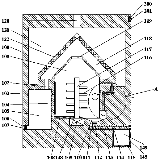
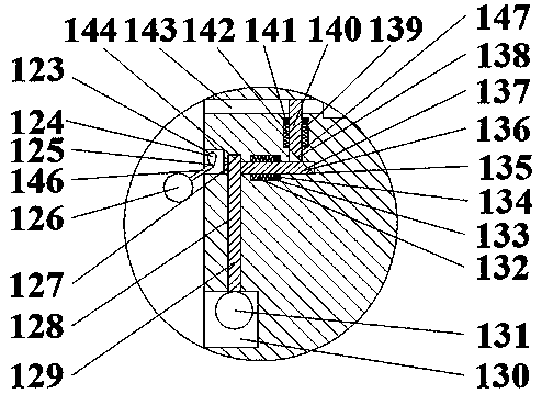

Image

  • High-efficiency condensed water recovery device
  • High-efficiency condensed water recovery device

Examples


Embodiment Construction

[0019] Such as Figure 1-Figure 2 As shown, a high-efficiency condensed water recovery device of the present invention includes a fuselage 100 and a first cavity 101 disposed in the fuselage 100, and a second cavity is disposed in the top wall of the first cavity 101 118, a first connection hole 119 is communicated between the first cavity 101 and the second cavity 118, and a third cavity 121 is annularly set in the top wall of the second cavity 118. The top wall of the three cavities 121 is provided with a water inlet 120 connected to the outside, and a condensing plate 122 is fixedly installed between the second cavity 118 and the third cavity 121, and the first cavity 101 and the third cavity 121 are fixedly installed. A second connection hole 143 is provided in communication between the second cavities 118, and a fourth cavity 123 opening to the left is provided in the right end wall of the first cavity 101, and the fourth cavity 123 can be The rotation is provided with a...


PUM


Abstract

The invention discloses a high-efficiency condensed water recovery device. The high-efficiency condensed water recovery device comprises a machine body and a first cavity formed in the machine body. Asecond cavity is formed in the top wall of the first cavity, and a first connecting hole is formed between the first cavity and the second cavity in a communicating mode. A third cavity is annularlyformed in the top wall of the second cavity, and a water inlet hole communicating with the outside is formed in the top wall of the third cavity. Condensation plates are fixedly mounted between the second cavity and the third cavity, and a second connecting hole is formed between the first cavity and the second cavity in a communicating mode. The high-efficiency condensed water recovery device issimple in structure and convenient to operate. Automatic water loading of the device is realized by adopting a floating ball structure, and steam is cooled by an original solution, so that energy is saved; and meanwhile, a material receiving structure is designed to collect the precipitated solid matter, the processes are coordinated with each other without affecting, the energy is saved, and thepractical performance of the device is improved.

Description

technical field [0001] The invention relates to the field of water treatment, in particular to a high-efficiency condensed water recovery device. Background technique [0002] With the development of science and technology and the progress of society, the country has been promoting the development of high technology. In the field of water treatment, there has always been a relatively difficult technical problem, that is, ordinary condensate recovery devices cannot be self-supplied to realize water supply and drainage, and cannot be efficient. Evaporation is completed in an energy-saving manner, and this device effectively solves this problem. Contents of the invention [0003] The technical problem to be solved by the present invention is to provide a high-efficiency condensed water recovery device, which can solve the above-mentioned problems in the prior art. [0004] The present invention is achieved through the following technical solutions: a high-efficiency condense...

Claims


Application Information

Patent Timeline
Patent Type & Authority Applications(China)
IPC IPC(8): F28B9/08
CPCF28B9/08
Inventor 刘迪远
Owner 黄山市雅龙智能科技有限公司
Why Eureka
Eureka Blog
Learn More