A tracking three-dimensional scanning method and system in a vibrating environment

A three-dimensional scanning and tracking technology, applied in the field of optical scanning, can solve the problems of cumbersome pasting of marking points, failure to meet the measurement requirements, and increase the workload of scanning and measurement, etc., to achieve expandable working space, wide application range, and convenience The effect of 3D reconstruction

Active Publication Date: 2020-06-12
ZG TECH CO LTD
View PDF5 Cites 0 Cited by
  • Summary
  • Abstract
  • Description
  • Claims
  • Application Information

AI Technical Summary

Problems solved by technology

[0002] The 3D optical scanner has been able to conveniently solve the high-precision measurement of most objects with poor surface texture, but it must paste a large number of uniformly distributed reflective marker points on the surface of the object to be measured for frame splicing during scanning, and the marker The point process is cumbersome, takes a lot of time, and increases the workload of scanning measurement
[0003] The vibration of the workshop leads to the constant change of the position of the measured object. In the case where only a small number of mark points are pasted locally, the 3D scanner will not be able to scan or The scan result does not meet the actual measurement requirements

Method used


Image

  • A tracking three-dimensional scanning method and system in a vibrating environment
  • A tracking three-dimensional scanning method and system in a vibrating environment
  • A tracking three-dimensional scanning method and system in a vibrating environment

Examples


Embodiment Construction

[0067] The principles and features of the present invention are described below in conjunction with the accompanying drawings, and the examples given are only used to explain the present invention, and are not intended to limit the scope of the present invention.

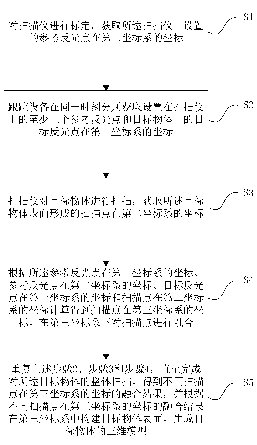
[0068] Such as figure 1 As shown, a tracking type three-dimensional scanning method in a vibration environment includes the following steps:

[0069] Step 1: Calibrate the scanner, and obtain the coordinates of the reference reflective point set on the scanner in the second coordinate system;

[0070] Step 2: The tracking device respectively obtains the coordinates of at least three reference reflective points set on the scanner and the target reflective point on the target object in the first coordinate system at the same time;

[0071] Step 3: The scanner scans the target object, and obtains the coordinates of the scanning point formed on the surface of the target object in the second coordinate system;

[0072]...


PUM


Abstract

The invention relates to a tracking type three-dimensional scanning method and system in a vibration environment. The method comprises the following steps: tracking equipment obtains a reference light-reflecting point arranged on a scanner and the coordinates of a target light-reflecting point on a target object in a first coordinate system; the scanner scans the target object to obtain the coordinates of scanning points formed on the surface of the target object in a second coordinate system; and according to the coordinates of the reference light-reflecting point in the first coordinate system, the coordinates of the reference light-reflecting point in the second coordinate system, the coordinates of the target light-reflecting point in the first coordinate system and the coordinates ofthe scanning points in the second coordinate system, obtaining the coordinates of the scanning points in the third coordinate system, performing fusion of the scanning points, and after the scanning is finished, constructing the surface of the target object in the third coordinate system to generate a three-dimensional model of the target object. The method provided by the invention can prevent alarge number of mark points from being pasted on the surface of the object, realize high-precision, high-efficiency and convenient three-dimensional reconstruction in a vibration environment, and theworking space can be expanded.

Description

technical field [0001] The invention relates to the field of optical scanning technology, in particular to a tracking three-dimensional scanning method and system in a vibration environment. Background technique [0002] The 3D optical scanner has been able to conveniently solve the high-precision measurement of most objects with poor surface texture, but it must paste a large number of uniformly distributed reflective marker points on the surface of the object to be measured for frame splicing during scanning, and the marker The point process is cumbersome, takes a lot of time, and increases the workload of scanning measurement. [0003] The vibration of the workshop leads to the constant change of the position of the measured object. In the case where only a small number of mark points are pasted locally, the 3D scanner will not be able to scan or The scan result does not meet the actual measurement requirements. Contents of the invention [0004] The technical problem...

Claims


Application Information

Patent Timeline
Patent Type & Authority Patents(China)
IPC IPC(8): G01B11/00G06T17/00
CPCG01B11/002G06T17/00G06T2200/08
Inventor 郑顺义王晓南成剑华刘庆龙朱锋博
Owner ZG TECH CO LTD
Why Eureka
Try Eureka