
Coherent pulse laser radar

A laser radar and coherent pulse technology, applied in the field of radar, can solve problems such as return light pulse and intensity distortion

Pending Publication Date: 2018-11-06
南京牧镭激光科技股份有限公司
View PDF0 Cites 6 Cited by
  • Summary
  • Abstract
  • Description
  • Claims
  • Application Information

AI Technical Summary

Problems solved by technology

[0002] When coherent pulse laser radar is used for detection, there will be an inherent detection blind zone. In theory, there is a detection blind zone of pulse width * speed of light / 2m. All the rising and falling edges of the modulation device itself are limited, and the pulse width cannot be modulated small enough. In view of the objectively existing pulse width limitation, when the coherent pulse is emitted, the pulse will return light at the position where the output end face and the optical antenna are in contact. The distortion of pulse and intensity, after coherent processing with the local oscillator signal, will produce pulse broadening on the time domain signal, the actual blind zone is about 1.5 times the pulse width * speed of light / 2m, and the abnormal spectrum will be analyzed at the same time

Method used

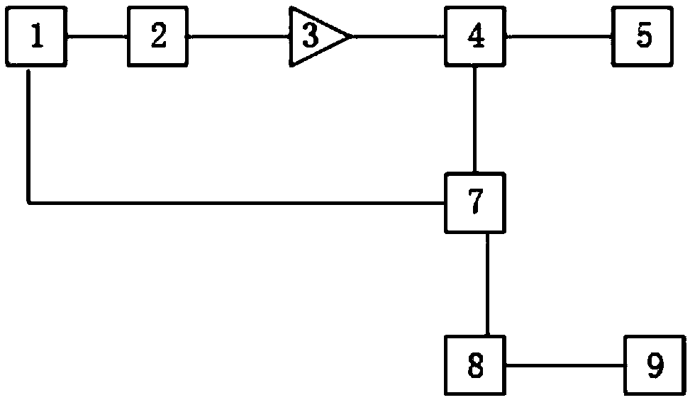

Image

  • Coherent pulse laser radar
  • Coherent pulse laser radar
  • Coherent pulse laser radar

Examples


Embodiment Construction

[0022] In order to make the purpose, technical solutions and advantages of the embodiments of the present invention clearer, the technical solutions in the embodiments of the present invention will be clearly and completely described below in conjunction with the drawings in the embodiments of the present invention. Obviously, the described embodiments It is a part of embodiments of the present invention, but not all embodiments. The components of the embodiments of the invention generally described and illustrated in the figures herein may be arranged and designed in a variety of different configurations.

[0023] Accordingly, the following detailed description of the embodiments of the invention provided in the accompanying drawings is not intended to limit the scope of the claimed invention, but merely represents selected embodiments of the invention. Based on the embodiments of the present invention, all other embodiments obtained by persons of ordinary skill in the art wi...


PUM


Abstract

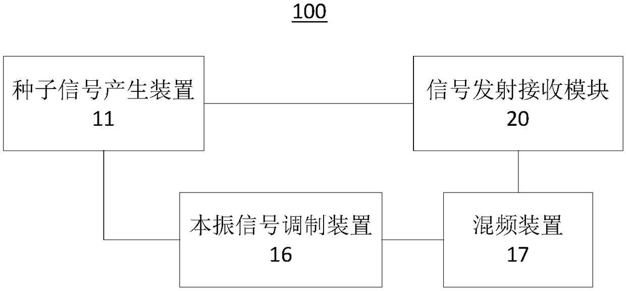
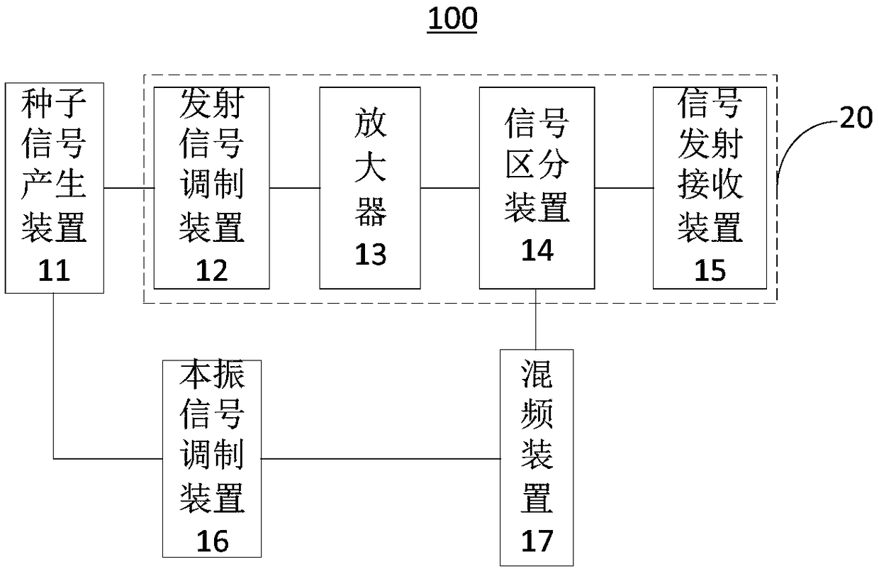
The invention relates to a coherent pulse laser radar which comprises a seed signal generation device, a signal transmitting and receiving module, a local oscillator signal modulation device and a frequency mixing device, wherein the seed signal generation device is used for generating a narrow linewidth seed laser signal; the signal transmitting and receiving module is used for modulating and amplifying the narrow linewidth seed laser signal and then transmitting the narrow linewidth seed laser signal as well as receiving an end surface light return signal reflected back by a to-be-tested object; the local oscillator signal modulation device is used for performing pulse modulation on the narrow linewidth seed laser signal to obtain a modulation signal; and the frequency mixing device is used for performing frequency beating processing on the end surface light return signal and the modulation signal to obtain a beating signal. According to the technical scheme, the local oscillator signal modulation device is additionally mounted on a local oscillator optical path, so that pulse modulation is performed on the narrow linewidth seed laser signal to obtain the modulation signal, and when the modulation signal and the end surface light return signal are subjected to frequency beating treatment, pulse distortion and strength distortion after frequency beating treatment are reduced,and the end surface information is reduced as far as possible finally.

Description

technical field [0001] The invention belongs to the technical field of radar, in particular to a coherent pulse laser radar. Background technique [0002] When coherent pulse laser radar is used for detection, there will be an inherent detection blind zone. In theory, there is a detection blind zone of pulse width * speed of light / 2m. All the rising and falling edges of the modulation device itself are limited, and the pulse width cannot be modulated small enough. For the objectively existing pulse width limitation, when the coherent pulse is emitted, the pulse will return light at the position where the output end face and the optical antenna are in contact. The distortion of pulse and intensity, after coherent processing with the local oscillator signal, will produce pulse broadening on the time domain signal, the actual blind zone is about 1.5 times the pulse width * speed of light / 2m, and the abnormal spectrum will be analyzed at the same time. Contents of the inventio...

Claims


Application Information

Patent Timeline
IPC IPC(8): G01S7/481G01S7/48
CPCG01S7/4802G01S7/481
Inventor 高炎锟钱勇朱海龙黄晨
Owner 南京牧镭激光科技股份有限公司
Learn More