Rolling linear guide pair reliability acceleration test assessment method

A linear guide pair, accelerated test technology, applied in the direction of instrumentation, design optimization/simulation, calculation, etc., can solve the problem of shortening the test time, it takes months or even years to complete the test when a single test sample is invested, and the lack of Mean interval between failures mileage and other issues to achieve the effect of ensuring accuracy and improving accuracy

Pending Publication Date: 2018-11-06
NANJING UNIV OF SCI & TECH
View PDF2 Cites 2 Cited by
  • Summary
  • Abstract
  • Description
  • Claims
  • Application Information

AI Technical Summary

Problems solved by technology

The reliability indicator mean time between failure (MTBF) of high-end CNC machine tools has reached thousands of hours. According to the traditional test technology to test the rolling linear guide pair, it will take months or even years to test only one test sample. Complete the test; when multiple test samples are put in, the high test cost is also unbearable
Therefore, the traditional reliability test method can no longer meet the test requirements of the rolling linear guide pair, and the accelerated reliability test technology with large stress and shortened test time has become an inevitable trend in the development of reliability test verification technology.
[0003] At present, there are existing evaluation methods for accelerated test reliability of ball screw pairs in China. Since the transmission mode and failure mode of ball screw pairs are very different from those of rolling linear guide rail pairs, the calculation method of its failure mode and stress acceleration factor and Equivalent conversion factors, etc. cannot be used for rolling linear guides
Therefore, the research on the special evaluation method for the reliability acceleration test of rolling linear guides is blank, and there is a lack of effective methods for calculating the mean distance between failures (MMBF) and mean time between failures (MTBF) of rolling linear guides.

Method used


Image

  • Rolling linear guide pair reliability acceleration test assessment method
  • Rolling linear guide pair reliability acceleration test assessment method
  • Rolling linear guide pair reliability acceleration test assessment method

Examples


Embodiment

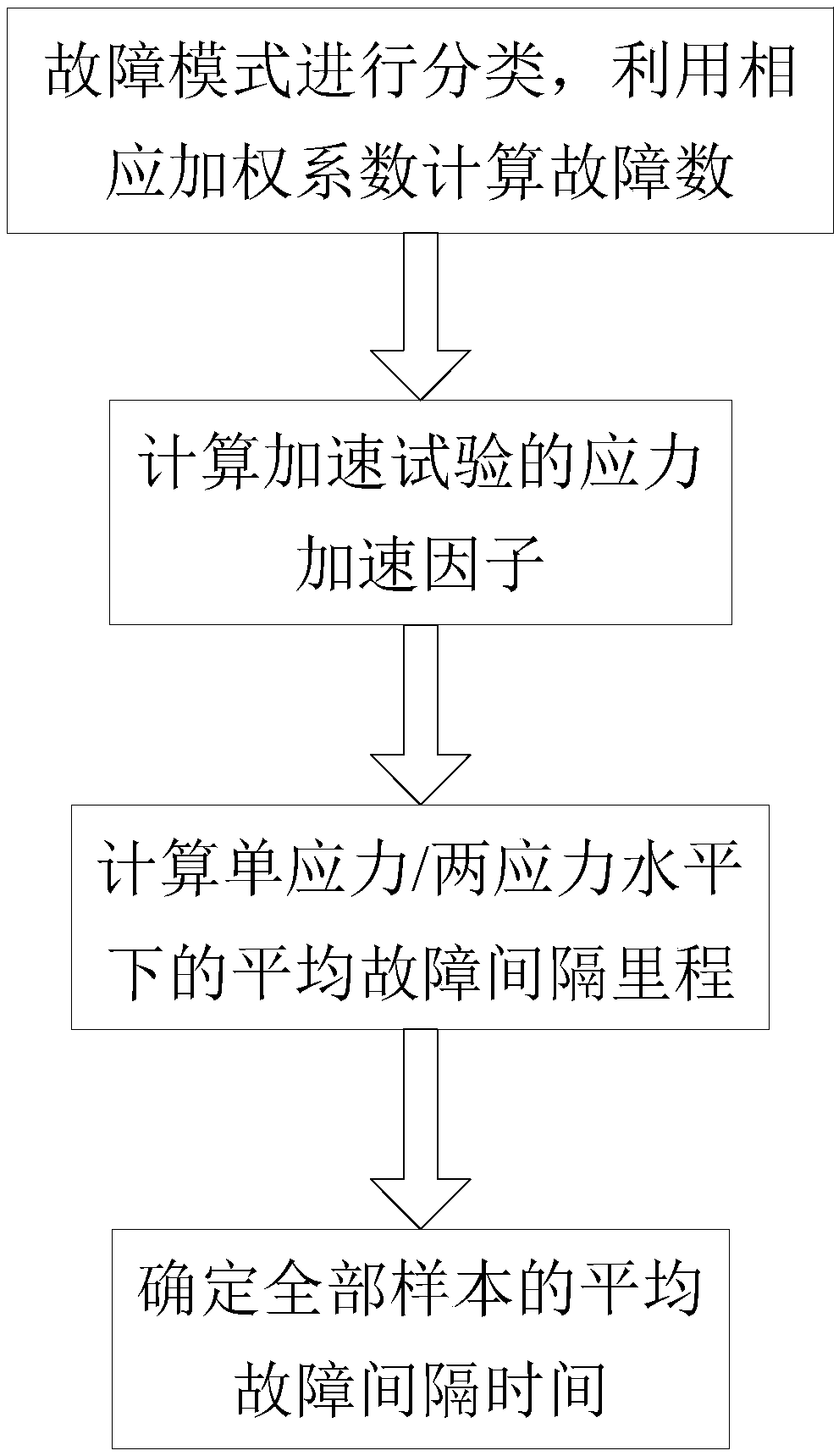
[0044] The accelerated test evaluation method for the reliability of the rolling linear guide pair includes the following contents:

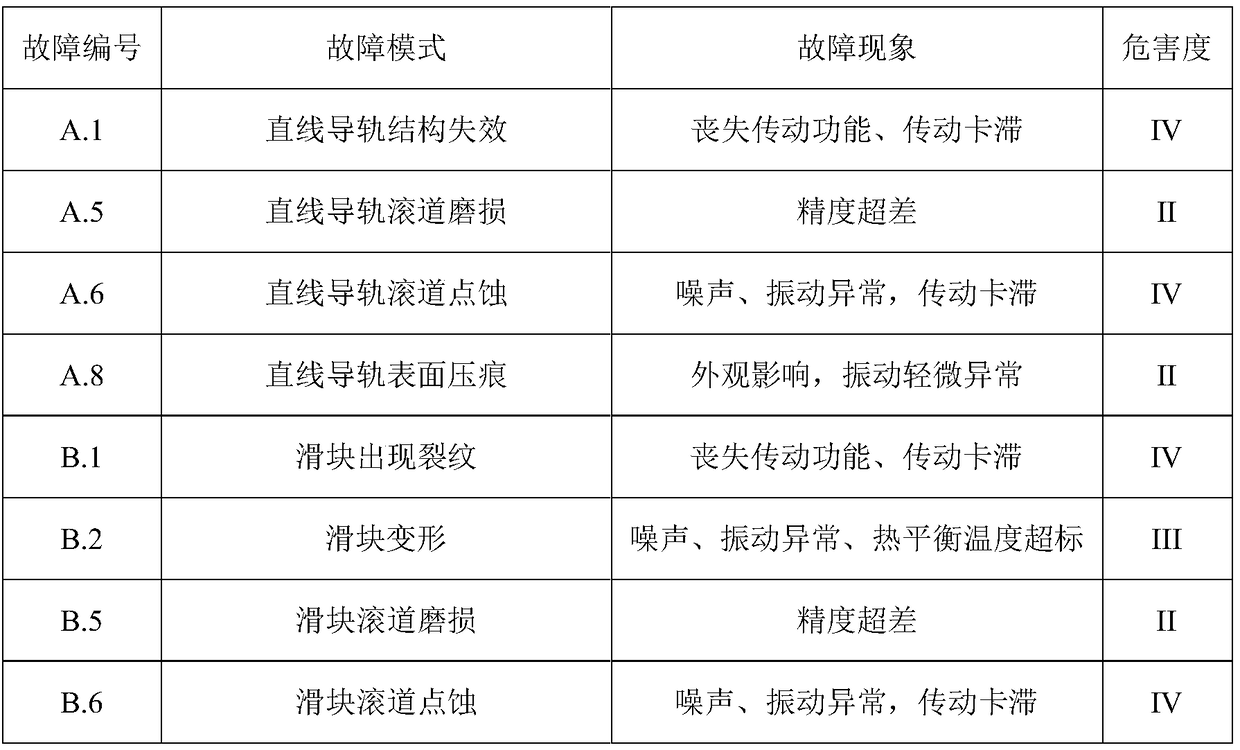
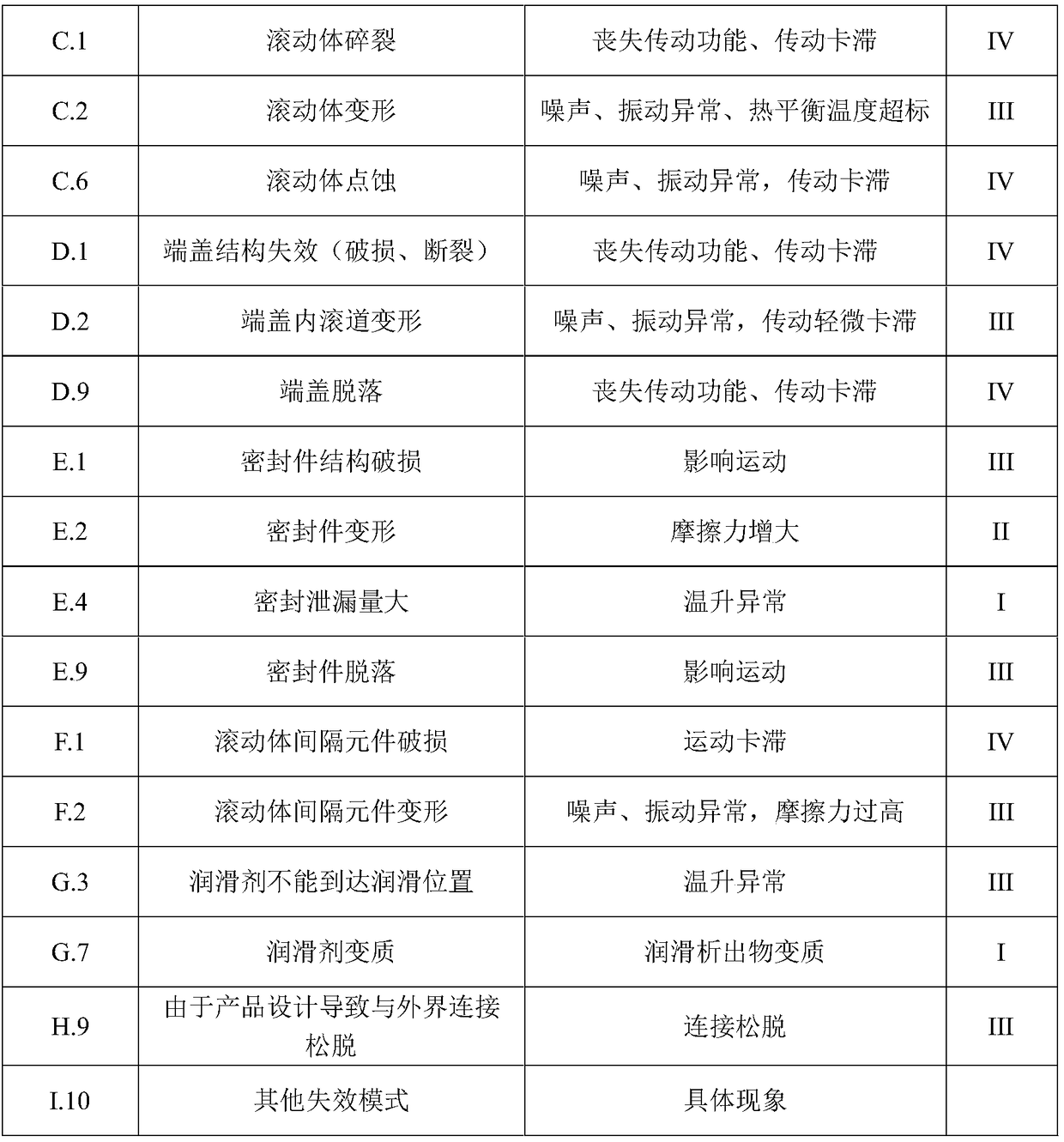
[0045] The fault classification and termination conditions of the rolling linear guide pair reliability test are as follows:

[0046] The timing censored reliability test method under two stress levels, the loading force is 30%C and 45%C respectively, the test cut-off mileage is set to be 400km, and the speed is 20m / min. The failure data of the three samples (the number of rotations of the failure / the failure number) are as follows: 295km / E4; 379km / B5; 685km / B5; 753km / B5. All samples produced irreparable faults when completing the specified mileage, a total of 3 samples, ie m=3. All sample failures are summarized, as shown in Table 4:

[0047] Table 4 Reliability Accelerated Test Fault Statistics Table

[0048]

[0049] 1. Stress acceleration factor calculation

[0050]The failure mechanism of the rolling linear guide pair will not change...


PUM


Abstract

The invention discloses a rolling linear guide pair reliability acceleration test assessment method. According to the method, first, fault modes in a reliability acceleration test are classified, andcorresponding weighting coefficients are utilized to calculate the number of faults; second, load conditions of the reliability acceleration test are utilized to calculate stress acceleration factorsof the acceleration test; third, the acceleration factors are utilized to calculate average fault interval mileage under a single stress level or two stress levels; and last, average fault interval time under all samples is utilized to evaluate the reliability of a rolling linear guide pair. Through the rolling linear guide pair reliability acceleration test assessment method based on an acceleration life time model, the reliability problem of the rolling linear guide pair with a fault or without a fault currently can be effectively solved, and therefore the accuracy of the reliability test result is improved.

Description

technical field [0001] The invention belongs to the field of reliability test evaluation, in particular to a reliability acceleration test evaluation method of a rolling linear guide pair. Background technique [0002] Rolling linear guides are the core functional components of CNC machine tools, and the reliability of rolling linear guides will directly affect the reliability of the entire CNC system. The reliability indicator mean time between failure (MTBF) of high-end CNC machine tools has reached thousands of hours. According to the traditional test technology to test the rolling linear guide pair, it will take months or even years to test only one test sample. Complete the test; when multiple test samples are put in, the high test cost is also unbearable. Therefore, the traditional reliability test method can no longer meet the test requirements of the rolling linear guide pair, and the accelerated reliability test technology with large stress and shortened test time ...

Claims


Application Information

Patent Timeline
Patent Type & Authority Applications(China)
IPC IPC(8): G06F17/50
CPCG06F30/20
Inventor 冯虎田王晓艺周华西周长光欧屹
Owner NANJING UNIV OF SCI & TECH
Why Eureka
Try Eureka