Rotating-disk type internal-pushing cup-falling machine

A turntable, drop-cup technology for use in coin-operated equipment for dispensing discrete items, coin-operated equipment for controlled dispensing of fluid/granular materials from containers, instruments, etc.

Pending Publication Date: 2018-11-06
JIANGSU HAOYU ELECTRONICS TECH
View PDF0 Cites 0 Cited by
  • Summary
  • Abstract
  • Description
  • Claims
  • Application Information

AI Technical Summary

Problems solved by technology

[0005] However, the cup dropping machine of the prior art is installed under the cup storage device during use, requiring the operator to press the switch to start the separation and dropping of the cups, and then proceed to the next

Method used


Image

  • Rotating-disk type internal-pushing cup-falling machine
  • Rotating-disk type internal-pushing cup-falling machine
  • Rotating-disk type internal-pushing cup-falling machine

Examples


Embodiment 1

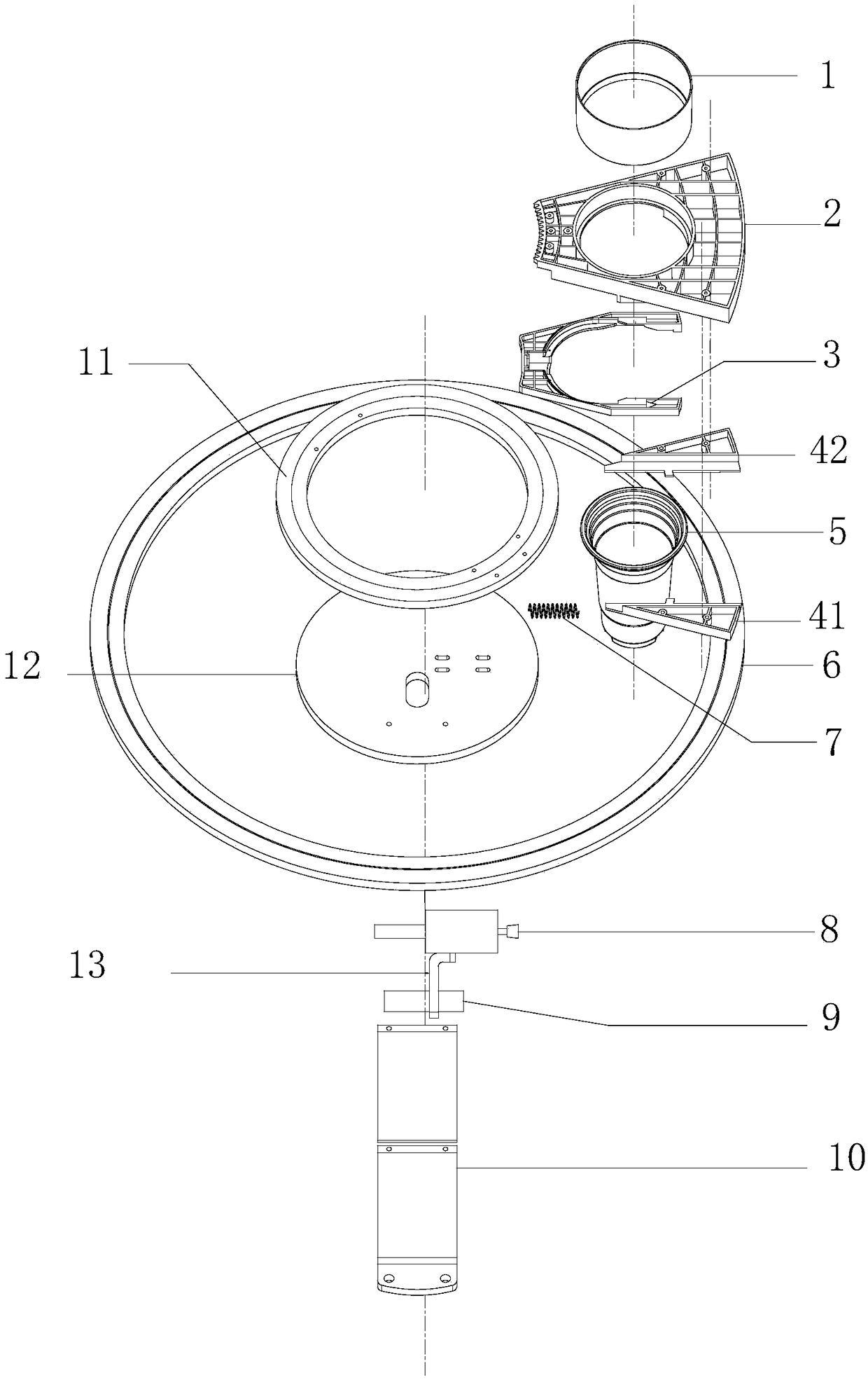
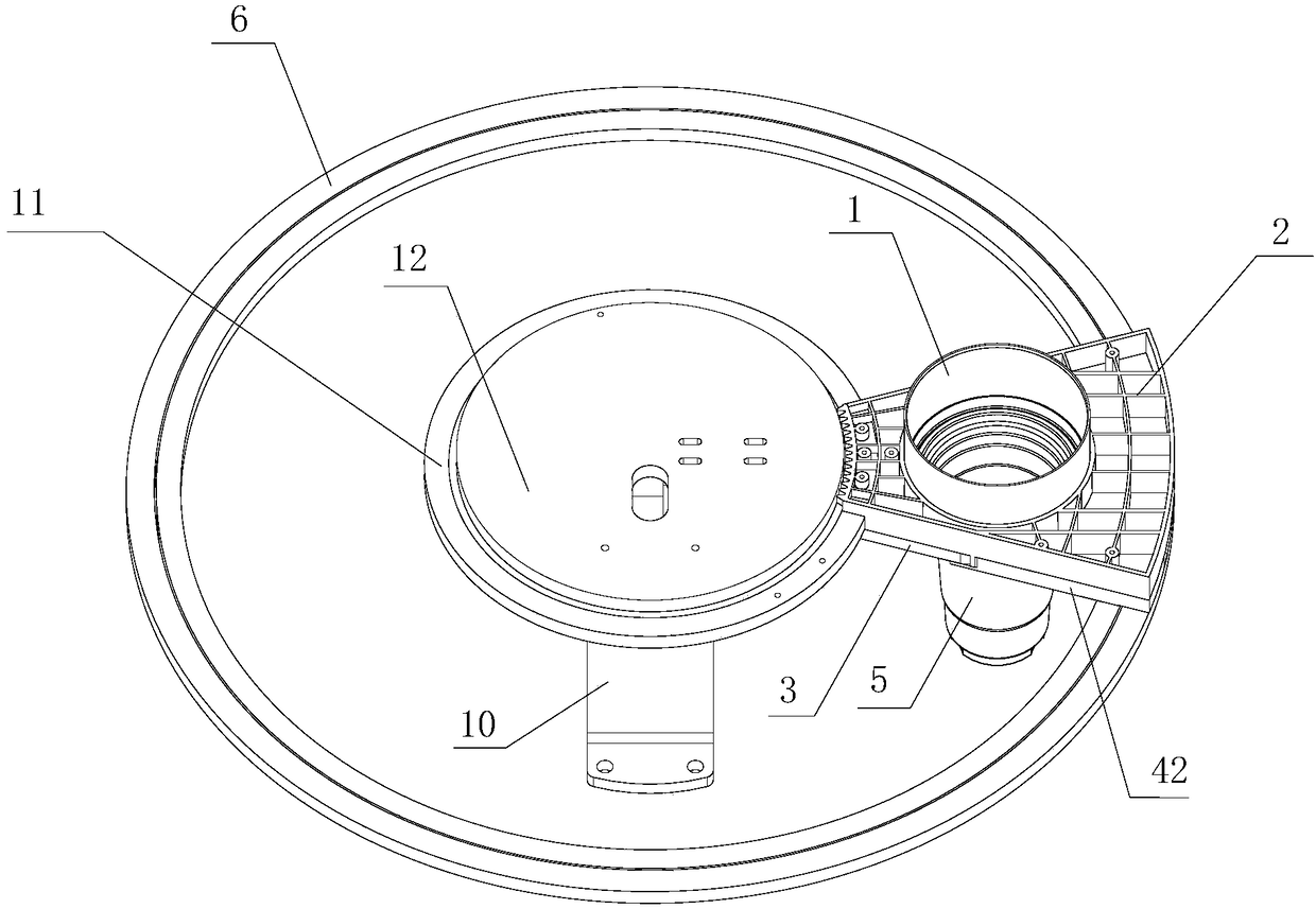
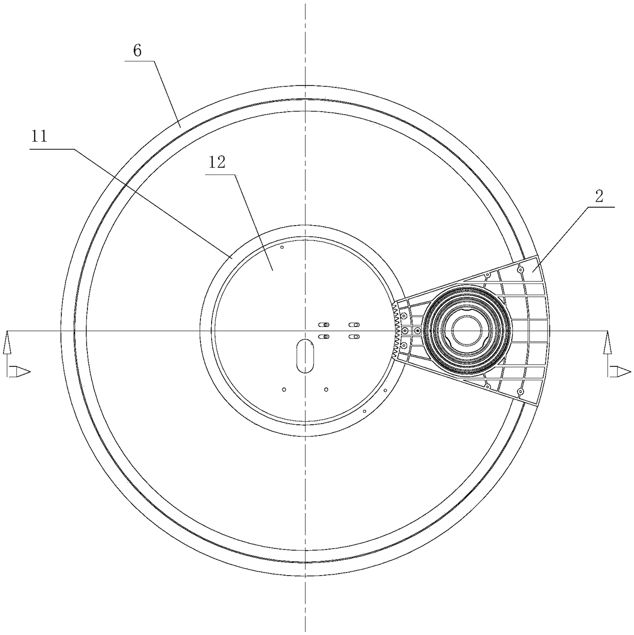
[0040] Embodiment 1: A turntable type internal push cup drop machine provided in this embodiment 1, its structural schematic assembly diagram when used for cup drop is as follows figure 1 As shown, the structural schematic general assembly diagram is shown in figure 2 as shown, figure 2 The schematic top view of the structure is as follows image 3 as shown, figure 2 The main view of the schematic diagram of the structure is as follows Figure 4 as shown, image 3 The A-A sectional view in the Figure 5 As shown, the rotary table-type internal push cup machine includes a bracket 10, a push rod mechanism 8, a turntable installed on the bracket 10, and a cup drop device installed on the turntable. In this embodiment, the turntable type inner push cup machine also includes a turntable mounting plate 12 installed on the bracket 10, the turntable includes an inner turntable 11 and an outer turntable 6 that are slidingly fitted on the turntable set plate 12, and the cup drop...

Embodiment 2

[0057] Embodiment 2: structure is basically the same as Embodiment 1, and the similarity is no longer repeated, and the difference is:

[0058] The turntable-type internal cup-dropping machine provided in this embodiment includes more than two cup-dropping devices installed on the turntable (these cup-dropping devices can be distributed circumferentially on the turntable). The cup drop machine includes more than two cup drop devices installed between the outer turntable 6 and the inner turntable 11. In this embodiment, the details are as follows: Figure 6 As shown, it includes 4 cup drop devices, of course, 6 or 8 can also be configured according to needs; at the same time, there are also devices on the turntable (such as between the outer turntable 6 and the inner turntable 11) for installing milk tea powder, fruit juice powder, etc. The food mounting seat 15 of various food bags is to achieve a more flexible and rich product application range. Under the structural configur...


PUM


Abstract

The invention discloses a rotating-disk type internal-pushing cup-falling machine. The machine comprises a support, a push rod mechanism, a rotating disk installed onto the support and one and more than one cup-falling device installed onto the rotating disk. Each cup-falling device comprises a cup-falling base with a cup-falling hole installed on the rotating disk and a cup-falling sliding blockwhich slides relative to the cup-falling base and is used for separating a falling cup. An elastic part is arranged between each cup-falling sliding block and each cup-falling base. The falling cup device can rotate along with the rotating disk till the device corresponds to the push rod mechanism. At this time, the other side, away from each elastic part, of each cup-falling sliding block is opposite to a rod end of the push rod mechanism. There is no need for a user to provide external force. The falling cup can be conveniently separated. The structure is reasonable and indigenous. The spaceutilization rate is high. The machine is convenient to promote and apply.

Description

technical field [0001] The invention relates to a cup dropping device, in particular to an automatic cup dropping machine. Background technique [0002] With the continuous development of human living standards, many beverage shops and automatic beverage vending machines have appeared on subways and street corners. Especially with the emergence of various convenient payment methods, automatic beverage vending machines have appeared more widely in streets and alleys. horn. [0003] However, regardless of the beverage store or the automatic beverage vending machine, the beverage machine and brewing machine used all use the cup drop device, also called the cup drop machine, especially on the automatic vending beverage machine and brewing machine, the structure of the cup drop device is directly Affects the ease of use of the machine. [0004] Even in beverage shops that employ staff, most of them use cup holders placed on the cup drop device to store and drop cups, avoiding c...

Claims


Application Information

Patent Timeline
IPC IPC(8): G07F13/10
CPCG07F13/10
Inventor 魏宏辉魏天浩魏妗羽
Owner JIANGSU HAOYU ELECTRONICS TECH
Why Eureka
Try Eureka