
Weighing device with buffer mechanism and using method thereof

The technology of a buffer mechanism and a weighing device, which is applied in the field of spinning processing equipment, can solve the problems of reducing production efficiency, handling troubles, and increasing processing steps, and achieves the effects of improving production efficiency, convenient use, and reducing processing steps.

Active Publication Date: 2021-03-23
FUJIAN JINJIANG TECH
View PDF17 Cites 0 Cited by
  • Summary
  • Abstract
  • Description
  • Claims
  • Application Information

AI Technical Summary

Problems solved by technology

[0003] The existing silk cake weighing device has complex structure, large device size, inconvenient movement, troublesome use, and the accuracy of the weighing device is prone to errors after long-term weighing, which leads to troublesome post-processing and low practicability; Moreover, the existing weighing device is separated from the conveying device and needs to be weighed separately. This weighing method increases processing steps, reduces production efficiency, and is not convenient to use, and the existing weighing device is not equipped with automatic classification. The device cannot automatically separate the defective products in the product, and it has certain limitations in use. In view of the above problems, the existing equipment needs to be improved

Method used


Image

  • Weighing device with buffer mechanism and using method thereof
  • Weighing device with buffer mechanism and using method thereof
  • Weighing device with buffer mechanism and using method thereof

Examples


Embodiment Construction

[0031] The present invention will be further described below in conjunction with the accompanying drawings.

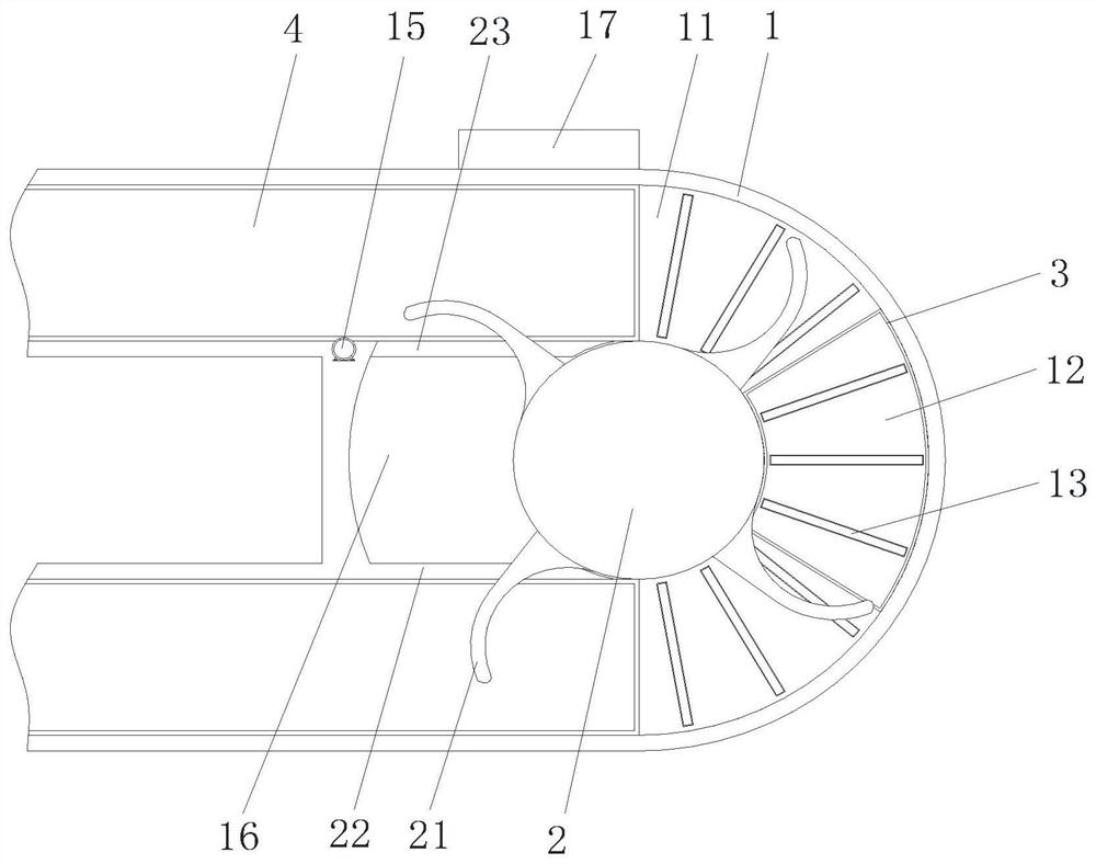
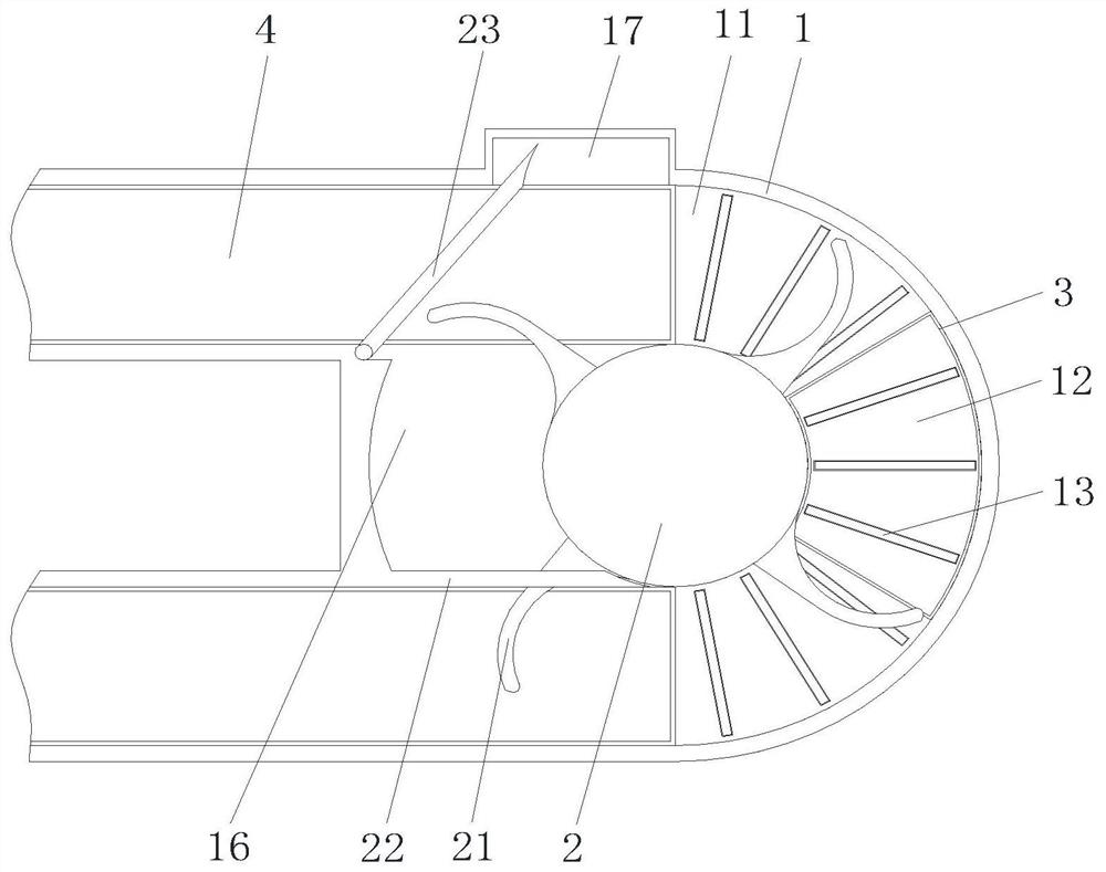
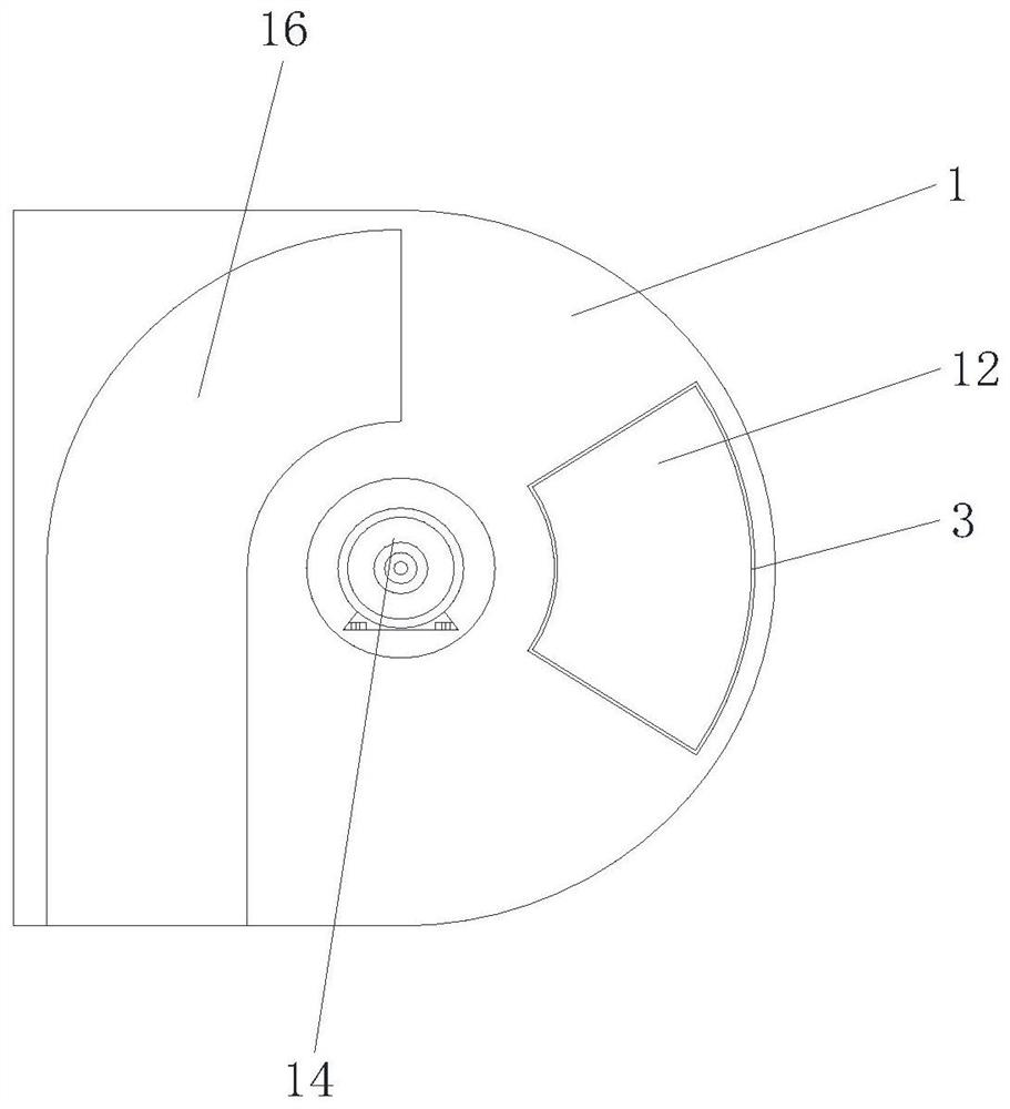
[0032] see Figure 1 to Figure 7As shown, the present invention provides an embodiment: a weighing device with a buffer mechanism, including a housing 1, a rotating member 2 and a groove 3, the upper side of the housing 1 is provided with a conveying channel 11, and the housing 1 The left front side and the left rear side are both provided with a conveying device 4 along the tangential direction to limit the moving direction of the silk cake. The bottom of the conveying channel 11 and the top of the buffer plate 12 are both rotatably connected with a roller 13; the rotating part 2 The lower side is rotationally connected with the housing 1, and the lower end of the rotating part 2 is connected with the driving motor 14 fixedly installed inside the housing 1. The outer side of the rotating part 2 is welded with an arc-shaped push plate 21, and the delivery channel 11 is...


PUM


Abstract

The invention provides a weighing device with a buffer mechanism and a using method thereof. The weighing device comprises a shell, a rotating member and a groove. A conveying channel is formed in theupper side of the shell, conveying devices are arranged on the left front side and the left rear side of the shell in the tangential direction, and rollers are rotatably connected to the bottom of the conveying channel and the top of a buffer plate. The lower side of the rotating piece is rotationally connected with the shell, the lower end of the rotating piece is connected with a driving motorfixedly installed in the shell, an arc-shaped push plate is welded to the outer side of the rotating piece, a fixed baffle staggered with the arc-shaped push plate is fixed to the left front side of the conveying channel, a movable baffle staggered with the arc-shaped push plate is rotatably connected to the left rear side of the conveying channel, and the upper end of the movable baffle is connected with a micro motor fixedly installed on the shell. The groove is formed in the right side of the shell and is communicated with the right side of the conveying channel. The weighing device is simple in structure, convenient to operate, capable of achieving spinning cake weighing and buffering effects and convenient to use.

Description

technical field [0001] The invention relates to the technical field of spinning processing equipment, in particular to a weighing device with a buffer mechanism and a usage method thereof. Background technique [0002] With the continuous development of the market, the product standard has become the standard of market quality. In the spinning process, it is necessary to place the silk cake on a weighing device to measure the weight. The weighing device will cause deviations in the measurement of the weighing device, so a buffer mechanism is needed. After massive searches, it is found that a typical example of the existing silk cake weighing device is CN210464654U, a silk cake weighing calibration device , including a detection device for detecting the weight of a plurality of silk cakes, characterized in that: a calibration device matched with the detection device, the calibration device includes a first frame, the front of the first frame is provided with a support assembl...

Claims


Application Information

Patent Timeline
IPC IPC(8): G01G23/00G01G23/06
CPCG01G23/00G01G23/06
Inventor 郑祥盘吴华新杨金富
Owner FUJIAN JINJIANG TECH
Learn More