
Display panel, driving method thereof, and electronic device

A technology of display panel and driving method, which is applied in the direction of static indicators, instruments, etc., and can solve the problems of unguaranteed display touch performance, unfavorable realization, squeezed touch time, etc.

Active Publication Date: 2018-11-06
BEIJING XIAOMI MOBILE SOFTWARE CO LTD
View PDF9 Cites 7 Cited by
  • Summary
  • Abstract
  • Description
  • Claims
  • Application Information

AI Technical Summary

Problems solved by technology

On the one hand, the design of data-driven chips is relatively complicated, which is not conducive to the realization of
[0006] Comprehensive comparison, the 1:3MUX solution needs to provide enough charging time for the display process, and within a fixed frame time, the display process time will also increase, thereby squeezing the touch time, resulting in insufficient touch time, causing the display to lag. Touch performance cannot be guaranteed

Method used


Image

  • Display panel, driving method thereof, and electronic device
  • Display panel, driving method thereof, and electronic device
  • Display panel, driving method thereof, and electronic device

Examples


Embodiment Construction

[0044] Reference will now be made in detail to the exemplary embodiments, examples of which are illustrated in the accompanying drawings. When the following description refers to the accompanying drawings, the same numerals in different drawings refer to the same or similar elements unless otherwise indicated. The implementations described in the following exemplary examples do not represent all implementations consistent with the present disclosure. Rather, they are merely examples of devices consistent with aspects of the present disclosure as recited in the appended claims.

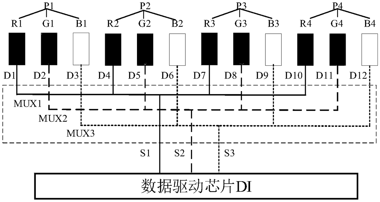
[0045] figure 2 It is a schematic diagram showing a connection relationship between a data driving chip and a pixel unit in a display panel according to an exemplary embodiment. see figure 2 , the display panel includes a data driver chip DI, multiple multiplexers MUXn ( figure 2 The labels MUX1, MUX2 and MUX3 are used to indicate different MUX) and multi-column pixel units Pn ( figure 2 Labels ...


PUM


Abstract

The present disclosure relates to a display panel, a driving method thereof, and an electronic device. The display panel comprises a data driving chip, a plurality of multiplexers (MUX) and a plurality of columns pixel units. The data driving chip is electrically connected to the plurality of MUXs through data transmission lines. The plurality of MUXs are electrically connected to the plurality ofcolumn pixel units through data lines. The ratio of the number of transmission lines to the number of data lines is 3:12; and the every two adjacent data lines receive pixel voltages transmitted by different data transmission lines. In this embodiment, the number of the data transmission lines can be reduced while the number of the data lines is kept constant, thereby reducing the size of the data driving chip and reducing the size of a display frame. In addition, in this embodiment, the charging time and the driving capability in a display process can be taken into consideration, the time ofthe display process is not increased and the driving capability of the data driving chip does not need to be increased, so that the touch time is not shortened and the touch performance of the display is ensured.

Description

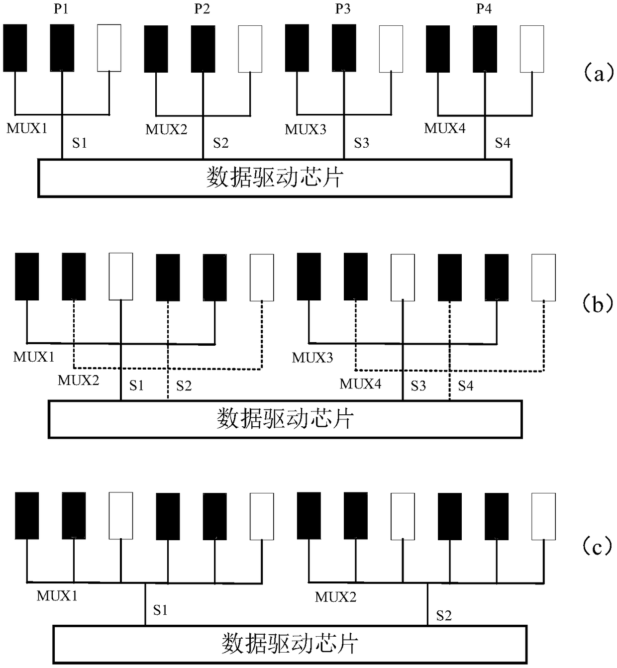
technical field [0001] The present disclosure relates to the field of display technology, and in particular, to a display panel, a driving method thereof, and an electronic device. Background technique [0002] At present, the data driving chip in the display outputs the pixel voltage to the pixel unit through the data line. Due to the large number of data lines in the display, correspondingly, the data driver chip needs more pins. In order to reduce the number of data-driven chips, a multiplexer MUX is set between the data-driven chip and the data line in the related art, see figure 1 , the data driver chip can connect three pixel subunits RGB through MUX (which can be called a 1:3MUX scheme). For example figure 1 As shown in (a), the channels S1, S2, S3 and S4 are respectively connected to the three pixel subunits RGB of the pixel units P1, P2, P3 and P4; figure 1 As shown in (b), channels S1 and S2 are mixed to connect pixel units P1 and P2, where S1 is connected to R...

Claims


Application Information

Patent Timeline
IPC IPC(8): G09G3/20
CPCG09G3/2074G09G3/2096
Inventor 卞青芳
Owner BEIJING XIAOMI MOBILE SOFTWARE CO LTD
Learn More