Preformed armor rod mounting winder

A pre-twisted wire and winder technology, applied in the direction of overhead lines/cable equipment, etc., can solve problems such as difficulties in the installation process, and achieve the effect of convenient operation, free application, and extremely easy to use

Active Publication Date: 2018-11-06
YINGKOU ELECTRIC POWER SUPPLY COMPANY OF STATE GRID LIAONING ELECTRIC POWER SUPPLY +1
View PDF4 Cites 0 Cited by
  • Summary
  • Abstract
  • Description
  • Claims
  • Application Information

AI Technical Summary

Problems solved by technology

[0002] In order to ensure the safety of the important crossing section of the transmission line, pre-twisted wires with drainage must be installed on the strain tower conductors of the line. , relatively hard, the installation process is very difficult

Method used


Image

  • Preformed armor rod mounting winder

Examples


Embodiment 1

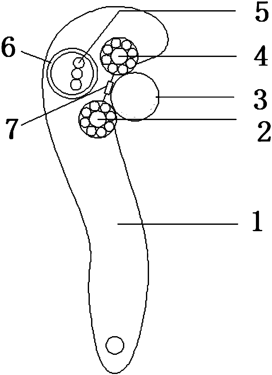
[0017] The invention provides a pre-twisted wire installation winder, characterized in that: the pre-twisted wire installation winder includes a wrench 1, a bearing three 2, a wire 3, a bearing two 4, a pre-twisted wire 5, and a bearing four 6 , bearing one 7;

[0018] Among them: the middle and upper part of the wrench 1 is a concave arc structure, bearing three 2, bearing two 4 and bearing one 7 are installed at the concave arc structure, bearing three 2, bearing two 4 and bearing one 7 are in rolling friction contact with the wire 3 Bearing 4 6 is installed in the back of the middle and upper part of wrench 1, and pre-twisted wire 5 is arranged in the bearing 4 6.

[0019] The said wrench 1 has a flat tail structure with a through hole.

[0020] The diameters of the first bearing 7 are smaller than the diameters of the third bearing 2 and the second bearing 4 .

[0021] The number of 5 pre-twisted wires is 2.

[0022] The tail of the wrench 1 is provided with a flexible ...

Embodiment 2

[0025] The invention provides a pre-twisted wire installation winder, characterized in that: the pre-twisted wire installation winder includes a wrench 1, a bearing three 2, a wire 3, a bearing two 4, a pre-twisted wire 5, and a bearing four 6 , bearing one 7;

[0026] Among them: the middle and upper part of the wrench 1 is a concave arc structure, bearing three 2, bearing two 4 and bearing one 7 are installed at the concave arc structure, bearing three 2, bearing two 4 and bearing one 7 are in rolling friction contact with the wire 3 Bearing 4 6 is installed in the back of the middle and upper part of wrench 1, and pre-twisted wire 5 is arranged in the bearing 4 6.

[0027] The said wrench 1 has a flat tail structure with a through hole.

[0028] The diameters of the first bearing 7 are smaller than the diameters of the third bearing 2 and the second bearing 4 .

[0029] Described bearing three 2 and bearing two 4 are deep groove ball bearings.

[0030] The number of 5 pr...

Embodiment 3

[0034] The invention provides a pre-twisted wire installation winder, characterized in that: the pre-twisted wire installation winder includes a wrench 1, a bearing three 2, a wire 3, a bearing two 4, a pre-twisted wire 5, and a bearing four 6 , bearing one 7;

[0035] Among them: the middle and upper part of the wrench 1 is a concave arc structure, bearing three 2, bearing two 4 and bearing one 7 are installed at the concave arc structure, bearing three 2, bearing two 4 and bearing one 7 are in rolling friction contact with the wire 3 Bearing 4 6 is installed in the back of the middle and upper part of wrench 1, and pre-twisted wire 5 is arranged in the bearing 4 6.

[0036] The said wrench 1 has a flat tail structure with a through hole.

[0037] The diameters of the first bearing 7 are smaller than the diameters of the third bearing 2 and the second bearing 4 .

[0038] Described bearing three 2 and bearing two 4 are deep groove ball bearings.

[0039] The number of 5 pr...


PUM


Abstract

The invention discloses a preformed armor rod mounting winder. The preformed armor rod mounting winder comprises a wrench, a third bearing, a conductor, a second bearing, preformed armor rod, a fourthbearing and a first bearing, wherein the middle upper part of the wrench is a concave arc structure, the third bearing, the second bearing and the first bearing are arranged at the concave arc structure and are in rolling friction contact with the conductor; the fourth bearing is arranged at the back of the middle upper part of the wrench, and the preformed armor rod are arranged in the fourth bearing. The winder disclosed by the invention has the advantages that the contact surface contacted with the conductor is a circular-arc section, the rolling bearing is arranged at the arc structure part to eliminate the abrasion between the winder and the conductor; the back of the circular arc contacted with the conductor is the hollow bearing, the preformed armor rod penetrate into the hollow bearing in the operation, and only the rolling friction of the bearing is existent between the preformed armor rod and the winder when the winder is rotated; the handle root of the winder is designed asthe flat arc, and can be inserted in the gap at the end of the preformed armor rod at the end of the preformed armor rod, and the end part of the preformed armor rod can be mounted in place when thepreformed armor rod is wound on a cross section direction of the conductor.

Description

technical field [0001] The invention relates to the field of power system equipment, in particular to a pre-twisted wire installation winder. Background technique [0002] In order to ensure the safety of the important crossing section of the transmission line, pre-twisted wires with drainage must be installed on the strain tower conductors of the line. , relatively hard, the installation process is very difficult. At present, this work project has just been launched. In the future promotion and use, the lack of special installation tools for pre-twisted wire is an urgent problem to be solved in the application of pre-twisted wire. Contents of the invention [0003] The purpose of the present invention is to facilitate the installation operation, and especially provides a pre-twisted wire installation winder. [0004] The invention provides a pre-twisted wire installation winder, characterized in that: the pre-twisted wire installation winder includes a wrench 1, a beari...

Claims


Application Information

Patent Timeline
Patent Type & Authority Applications(China)
IPC IPC(8): H02G1/02
CPCH02G1/02
Inventor 苑爱国沈刚金卓琛郭峰孙超谢晖刘伟杰徐明刘哲辰周纯智于涛关永宝侯葳孙雁翎张辉
Owner YINGKOU ELECTRIC POWER SUPPLY COMPANY OF STATE GRID LIAONING ELECTRIC POWER SUPPLY
Why Eureka
Try Eureka