Switch quasi-Z source-switched capacitor wide gain bidirectional DC converter for electric vehicle
A bidirectional DC conversion and electric vehicle technology, applied in the direction of converting DC power input to DC power output, adjusting electrical variables, instruments, etc., can solve problems such as low voltage gain and electrical stress, and the power density of the converter cannot be improved. Wide range, improved energy conversion efficiency, and improved operational reliability
- Summary
- Abstract
- Description
- Claims
- Application Information
AI Technical Summary
Problems solved by technology
Method used
Image

Examples
Embodiment 1
[0035] A switch quasi-Z source-switch capacitor wide gain bidirectional DC converter, see Figure 1 to Figure 4 , the structure of the transformer is as follows:
[0036] (1) Topology
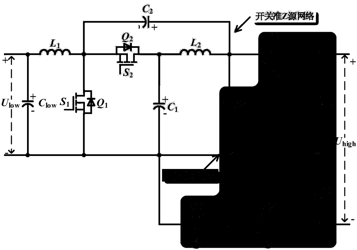
[0037] The topology of the switched quasi-Z source-switched capacitor bidirectional DC converter proposed by the embodiment of the present invention is as follows: figure 1 shown. From figure 1 It can be seen that the converter proposed by the embodiment of the present invention mainly includes two parts: a switched quasi-Z source network and a switched capacitor unit.
[0038] Among them, the switch quasi-Z source network includes: inductor L 1 , inductance L 2 , capacitance C 1 , capacitance C 2 , Power switch Q 2 . The switched capacitor unit includes: capacitor C 3 , capacitance C4 , capacitance C 5 , Power switch Q 3 , Power switch Q 4 and the power switch Q 5 .
[0039] where the power switch Q 2 , Q 3 and Q 5 The drive signal S 2 , S 3 and S 5 for the same drive sign...
Embodiment 2
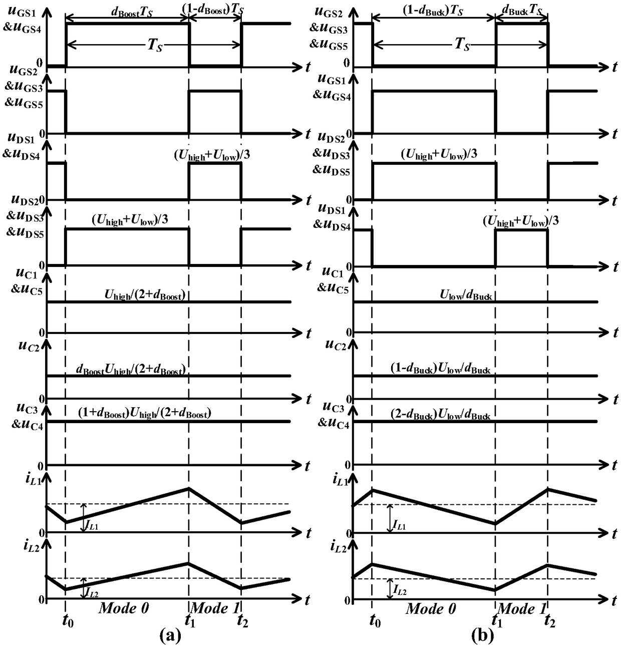
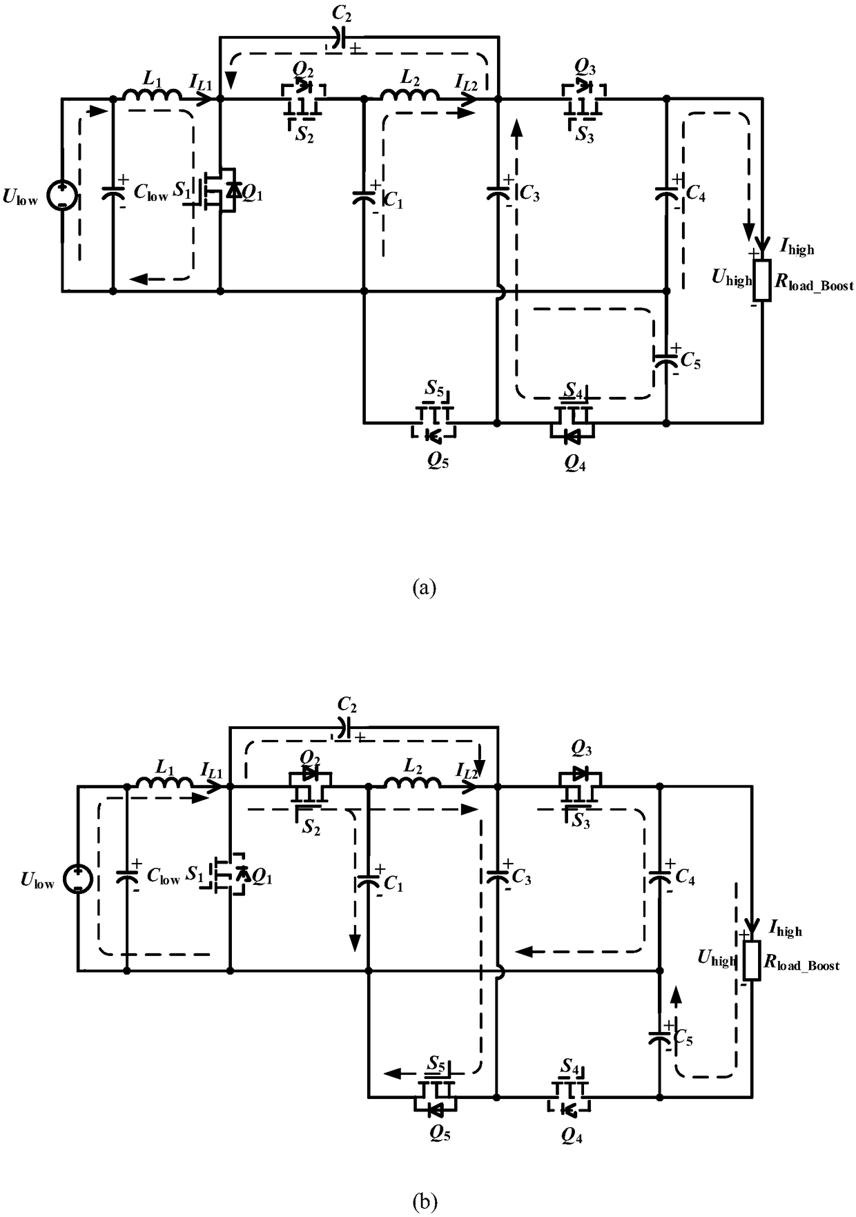
[0071] Below to figure 1 The switching quasi-Z source-switching capacitor wide-gain bidirectional DC converter topology shown, figure 2 The main characteristic waveforms of the new topology in stable operation and figure 2 , 3 The topology equivalent circuit diagram of FIG. 1 illustrates the principles of the embodiments of the present invention. In each carrier cycle, the converter experiences two switching states in total, and the boost mode (Boost) and buck mode (Buck) of the converter will be described respectively below.
[0072] 1. Boost mode
[0073] When the switching quasi-Z source-switched capacitor bidirectional DC converter operates in boost mode, the characteristic waveform of the proposed converter in this state is as follows figure 2 As shown in (a), the corresponding topological current flow path is as follows image 3 (a) (b) shown.
[0074] (1) When S 1 S 2 S 3 S 4 S 5 =10010, the power switch Q 1 forward conduction, Q4 reverse conduction, the ...
PUM
 Abstract
Description
Claims
Application Information
 - R&D
- Intellectual Property
- Life Sciences
- Materials
- Tech Scout
- Unparalleled Data Quality
- Higher Quality Content
- 60% Fewer Hallucinations
Browse by: Latest US Patents, China's latest patents, Technical Efficacy Thesaurus, Application Domain, Technology Topic, Popular Technical Reports.
© 2025 PatSnap. All rights reserved.Legal|Privacy policy|Modern Slavery Act Transparency Statement|Sitemap|About US| Contact US: help@patsnap.com