A Low Current Ripple Coupled Inductor Bidirectional DC Converter
A technology of bidirectional DC conversion and coupled inductance, which is applied in the direction of converting DC power input to DC power output, adjusting electrical variables, instruments, etc., can solve problems such as voltage level mismatch, reduce current ripple, increase gain, and avoid impact effect
- Summary
- Abstract
- Description
- Claims
- Application Information
AI Technical Summary
Problems solved by technology
Method used
Image

Examples
Embodiment 1
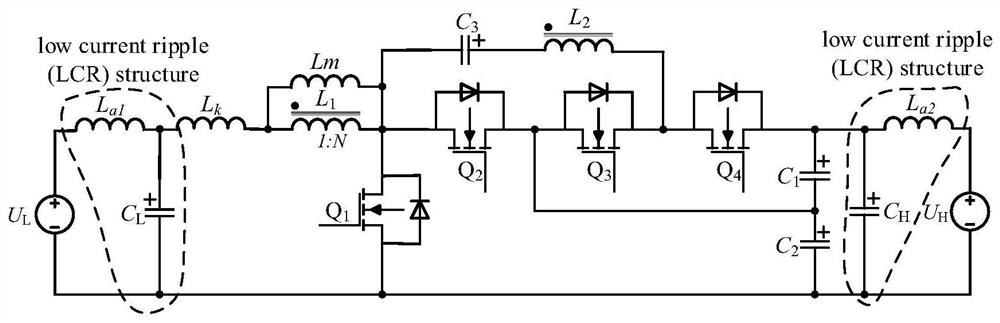
[0061] A low current ripple coupled inductor bidirectional DC converter, see figure 1 , the low current ripple coupled inductor bidirectional DC converter consists of:
[0062] 1) An inductance L is connected in parallel at the low-voltage interface a1 and capacitance C L , an inductor L is connected in parallel at the high-voltage interface a2 and capacitance C H , inductance L a1 and capacitance C L , and inductance L a2 and capacitance C H Both constitute the LCR structure, that is, the LCR structure is added in both directions.
[0063] 2) On the low voltage side inductance L a1 Connect the equivalent leakage inductance L k One end of the equivalent leakage inductance L k The other end of the parallel connection equivalent excitation inductance L m One end and the primary inductance L 1 At one end, the equivalent magnetizing inductance L m The other end of the, and the primary side inductance L 1 Connect the other end of the capacitor C 3 One end of the capa...
Embodiment 2
[0068] Combine below Figure 1-Figure 7 The scheme in Example 1 is further introduced, see the following description for details:
[0069] (1) Topology
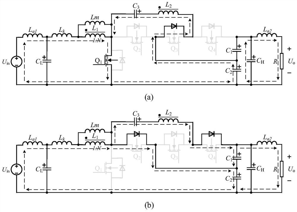
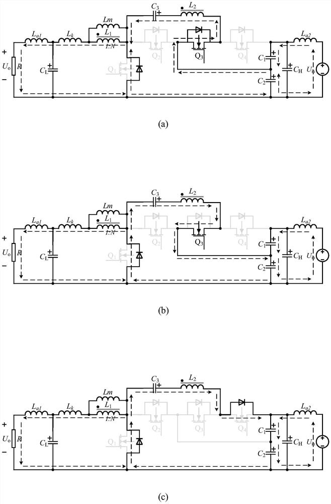
[0070] The embodiment of the present invention proposes as figure 1 The shown low current ripple coupled inductance bidirectional DC converter increases the gain by introducing a coupled inductance during operation, and at the same time increases the LCR structure to reduce the current ripple. figure 2 and image 3 It is the operation schematic diagram of the low current ripple coupled inductance bidirectional DC converter in two modes. Figure 4 and Figure 5 It is an important working waveform of the converter in the two modes of the low current ripple coupled inductor bidirectional DC converter.
[0071] (2) Gain derivation
[0072] In order to facilitate the analysis of the voltage gain and component stress of the converter in Boost mode, the leakage inductance of the coupled inductor and the additional inductance ...
Embodiment 3
[0097] Below to figure 1 low current ripple coupled inductor bidirectional DC converter and figure 2 , image 3 The schematic diagram of the operation of the converter is shown to illustrate the principles and best implementation modes of the embodiments of the present invention. The important waveforms during the operation of the converter are as Figure 4 , Figure 5 shown.
[0098] figure 2 Shown is the switching state of the converter in Boost mode. At this time the power switch Q1 for the main, power switch Q 2-4 acts as a freewheeling diode. Such as figure 2 (a) shows the power switch Q 1 The flow path of the converter current when it is turned on, the low-voltage power supply and the primary side of the coupled inductor L 1 Series via power switch Q 1 Constitute the charging circuit, capacitor C 2 via power switch Q 3 The freewheeling diode and the secondary side of the coupled inductor L 2 Series to capacitor C 3 Discharge, charge current flows throug...
PUM
 Abstract
Description
Claims
Application Information
 - R&D
- Intellectual Property
- Life Sciences
- Materials
- Tech Scout
- Unparalleled Data Quality
- Higher Quality Content
- 60% Fewer Hallucinations
Browse by: Latest US Patents, China's latest patents, Technical Efficacy Thesaurus, Application Domain, Technology Topic, Popular Technical Reports.
© 2025 PatSnap. All rights reserved.Legal|Privacy policy|Modern Slavery Act Transparency Statement|Sitemap|About US| Contact US: help@patsnap.com