Wide-gain common-ground asymmetric h-bridge bidirectional DC converter for energy storage systems
A bidirectional DC conversion and DC converter technology, applied in the direction of converting DC power input to DC power output, control/regulation systems, output power conversion devices, etc., can solve the problem of reducing the power density of converters and restricting the application of bidirectional DC converters , bidirectional DC converter input and output are not common ground and other problems
- Summary
- Abstract
- Description
- Claims
- Application Information
AI Technical Summary
Problems solved by technology
Method used
Image

Examples
Embodiment 1
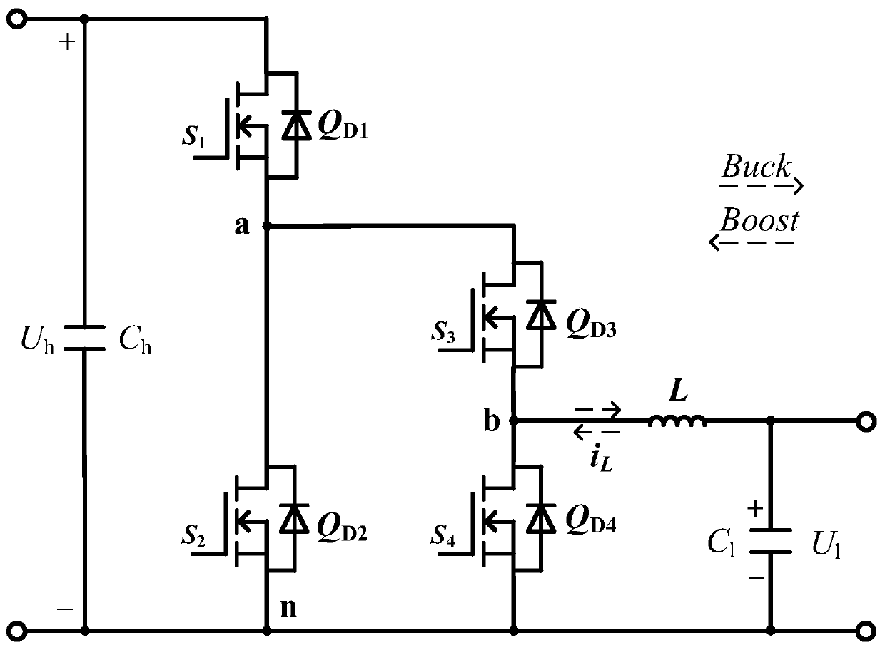
[0033] A wide-gain common-ground asymmetric H-bridge bidirectional DC converter for energy storage systems, see figure 1 , the common-ground asymmetric H-bridge bidirectional DC converter is as follows:
[0034] 1. Topology:
[0035] The common-ground asymmetrical H-bridge bidirectional DC converter alternately stores energy and releases energy through the inductor L to realize step-down (Buck) and boost (Boost).
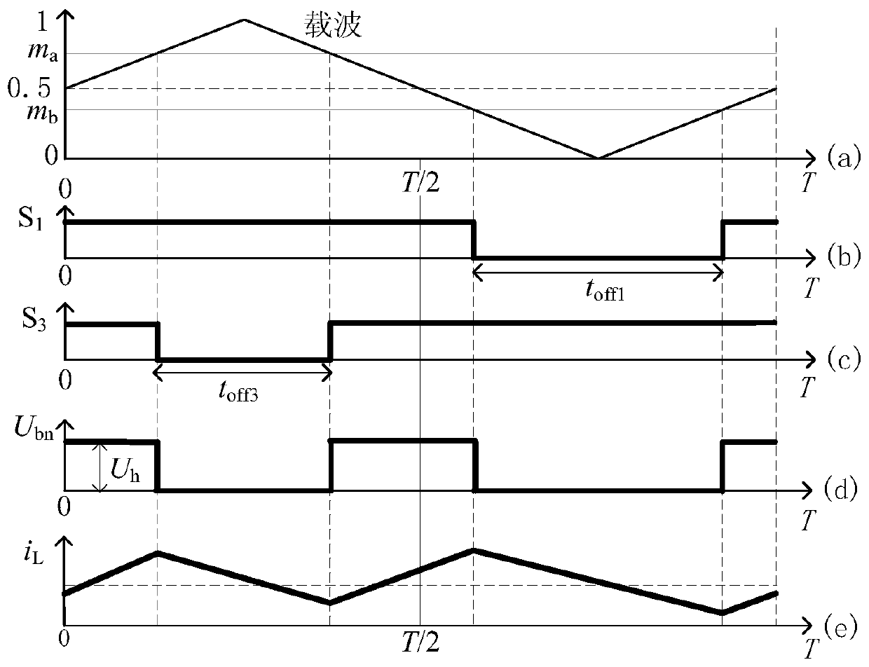
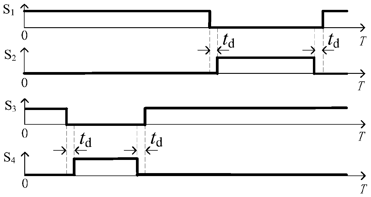
[0036] figure 2 , image 3 It is the schematic diagram of Buck mode operation of the common-ground asymmetric H-bridge bidirectional DC converter, the operation drive signal and the dead zone. Figure 4 , Figure 5 It is the schematic diagram of the Boost mode operation of the common-ground asymmetrical H-bridge bidirectional DC converter, the operating drive signal and the dead zone.
[0037] 2. Wide voltage gain
[0038] 1. Buck mode
[0039] When the common-ground asymmetrical H-bridge bidirectional DC converter operates in the step-down (Buck) state, its...
Embodiment 2
[0062] Below to figure 1 common-ground asymmetric H-bridge bidirectional DC converter and figure 2 , Figure 4 The shown modulation strategy describes the principles and best implementation modes of the embodiments of the present invention. In each carrier period, the converter experiences three switching states in total, and the Buck and Boost modes of the converter will be described respectively below.
[0063] 1. Buck mode
[0064] 1. Switch state S 1 S 3 =10, the inductor current i L by Q D4 freewheeling, i L Gradually decreases, the energy on the inductance L is gradually consumed on the low-voltage energy storage device, the energy storage on the inductance L decreases, and the converter has a voltage closed loop: U l -Q D4 -L-U l , recorded as a closed loop (1-a), in the closed loop (1-a), the inductor L releases energy and supplies energy to the low-voltage energy storage device. The total time experienced by the switching state t 10 =(1-d 3 )T.
[0065]...
PUM
 Abstract
Description
Claims
Application Information
 - R&D
- Intellectual Property
- Life Sciences
- Materials
- Tech Scout
- Unparalleled Data Quality
- Higher Quality Content
- 60% Fewer Hallucinations
Browse by: Latest US Patents, China's latest patents, Technical Efficacy Thesaurus, Application Domain, Technology Topic, Popular Technical Reports.
© 2025 PatSnap. All rights reserved.Legal|Privacy policy|Modern Slavery Act Transparency Statement|Sitemap|About US| Contact US: help@patsnap.com