Eureka AIR delivers breakthrough ideas for toughest innovation challenges, trusted by R&D personnel around the world.

Energy-saving electronic contaminating fluid treatment device

A technology for processing devices and polluted liquids, which can be used in mixers with rotary stirring devices, transportation and packaging, chemical/physical processes, etc., and can solve the problems of invariance, low efficiency, and high labor intensity.

Inactive Publication Date: 2018-11-09
广州星引科技有限公司
View PDF0 Cites 0 Cited by
  • Summary
  • Abstract
  • Description
  • Claims
  • Application Information

AI Technical Summary

Problems solved by technology

[0002] In modern industrial manufacturing, more electronic pollution liquids are often produced, and these electronic pollution liquids are usually stirred with a treatment agent. Traditionally, this operation is mostly manual operation, which is labor-intensive and inefficient. Now There are also many automatic mixing devices, but most of the mixing drums are built-in and are extremely unchanged when they are disassembled, cleaned, replaced and installed. There are major disadvantages and need to be improved.

Method used


Image

  • Energy-saving electronic contaminating fluid treatment device
  • Energy-saving electronic contaminating fluid treatment device

Examples


Embodiment Construction

[0015] All features disclosed in this specification, or steps in all methods or processes disclosed, may be combined in any manner, except for mutually exclusive features and / or steps.

[0016] Any feature disclosed in this specification (including any appended claims, abstract and drawings), unless expressly stated otherwise, may be replaced by alternative features which are equivalent or serve a similar purpose. That is, unless expressly stated otherwise, each feature is one example only of a series of equivalent or similar features.

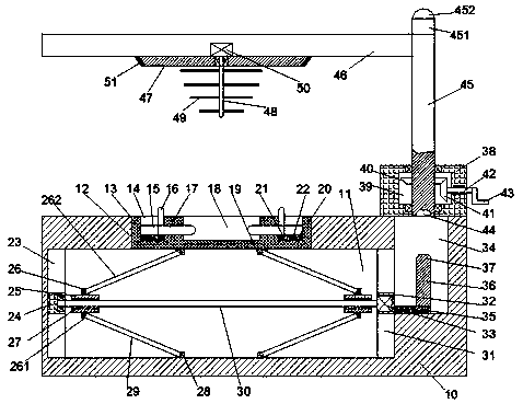
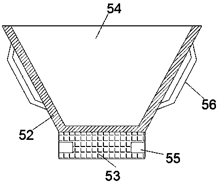
[0017] Such as Figure 1-2 As shown, an energy-saving electronic pollution liquid treatment device of the device of the present invention includes a mixing tube 52, a bottom plate 10, and an installation platform 38 fixedly arranged on the right side of the top end surface of the bottom plate 10, and the bottom plate 10 is provided with Receptacle 11, the inner top wall of the receptacle 11 is provided with a first chute 12 communicating with...


PUM


Abstract

The invention discloses an energy-saving electronic contaminating fluid treatment device. The energy-saving electronic contaminating fluid treatment device comprises a uniform stirring barrel, a bottom plate and a mounting platform which is fixedly arranged at the right side of a top end face of the bottom plate, wherein a containing groove is formed in the bottom plate; a top wall in the containing groove is provided with a first sliding groove which is communicated with the outer part; a first sliding push block is movably mounted in the first sliding groove; a first mounting cavity with anupward opening end is formed in the first sliding push block; the first mounting cavity is internally provided with a locking device; a second sliding groove and a third sliding groove are formed in left and right inner walls of the containing groove respectively; a second sliding push block and a third sliding push block are movably mounted in the second sliding groove and the third sliding groove respectively; screw sleeves are bilaterally symmetrically arranged in the containing groove and screw holes are formed in the screw sleeves.

Description

technical field [0001] The invention relates to the technical field of electronic pollution liquid treatment, in particular to an energy-saving electronic pollution liquid treatment device. Background technique [0002] In modern industrial manufacturing, more electronic pollution liquids are often produced, and these electronic pollution liquids are usually stirred with a treatment agent. Traditionally, this operation is mostly manual operation, which is labor-intensive and inefficient. Now There are also many automatic mixing devices, but most of the mixing drums are built-in and are extremely unchanged when they are disassembled, cleaned, replaced and installed. There are major disadvantages and need to be improved. Contents of the invention [0003] Aiming at the deficiencies of the above technologies, the present invention proposes an energy-saving electronic pollution liquid treatment device. [0004] An energy-saving electronic pollution liquid processing device ...

Claims


Application Information

Patent Timeline
Patent Type & Authority Applications(China)
IPC IPC(8): B01F15/00B01F7/18
CPCB01F27/806B01F27/90B01F35/42B01F35/10B01F2101/305
Inventor 陆伟城
Owner 广州星引科技有限公司
Why Eureka
Eureka Blog
Learn More