Dust removing device dedicated to computer numerical control cutter

A technology of a dust removal device and a cutting machine, which is applied in the directions of removing smoke and dust, cleaning methods and appliances, gas flame welding equipment, etc. Problems, reasonable design of device structure, high efficiency of smoke and dust capture

Pending Publication Date: 2018-11-09
青岛海洋技师学院 +1
View PDF1 Cites 6 Cited by
  • Summary
  • Abstract
  • Description
  • Claims
  • Application Information

AI Technical Summary

Problems solved by technology

[0004] The purpose of the present invention is to overcome the shortcomings in the prior art and seek to design a special dust removal device for CNC cutting machine, which solves the problem that the existing dust removal device for CNC cutting machine is difficult to move simul

Method used


Image

  • Dust removing device dedicated to computer numerical control cutter
  • Dust removing device dedicated to computer numerical control cutter
  • Dust removing device dedicated to computer numerical control cutter

Examples


Embodiment 1

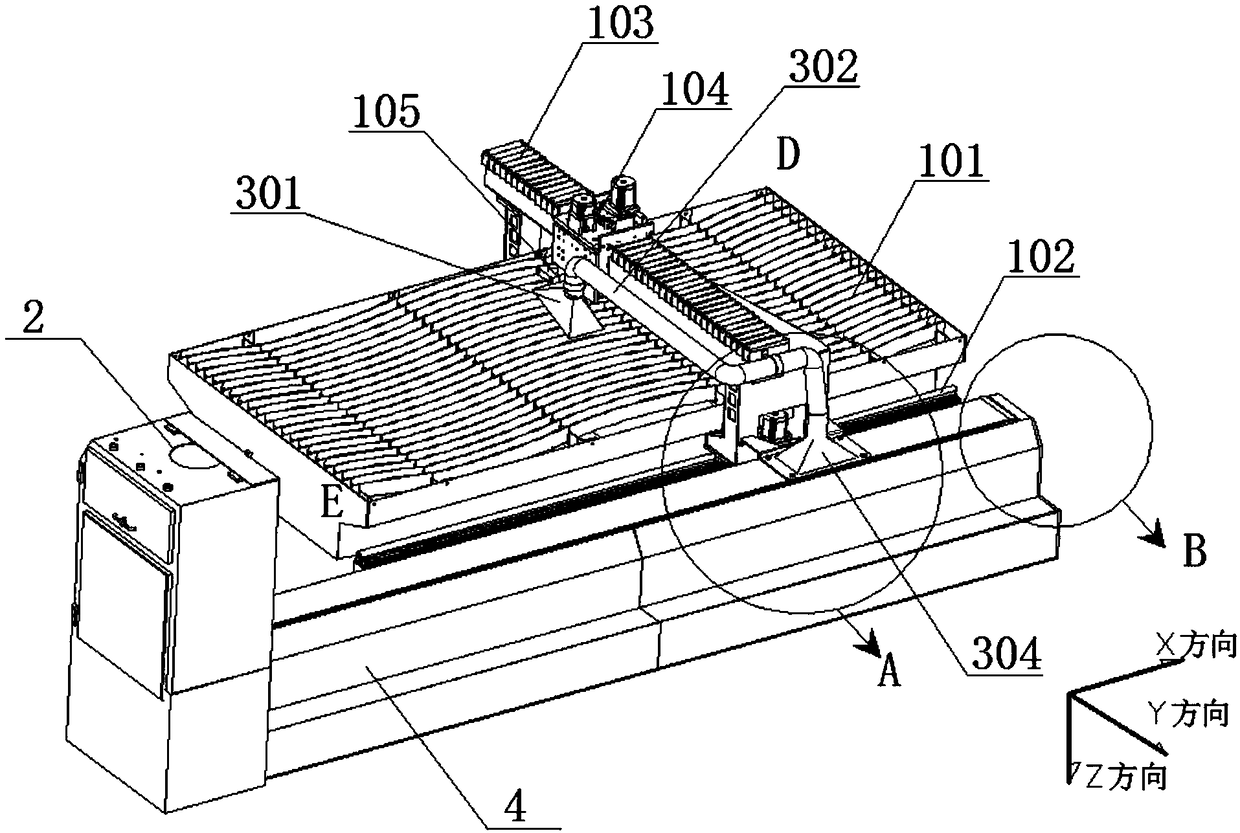
[0022] Such as figure 1 As shown, a special dust removal device for CNC cutting machine involved in this embodiment includes a dust collection device 3, a gas channel 4 and a dust collector 2, and the collection port of the dust collection device 3 fixed on the trolley 104 is always aligned with the cutting torch 105 for collection. Smoke, dust collection device 3 can drive the collection port of the dust collection device to move in the Y direction.

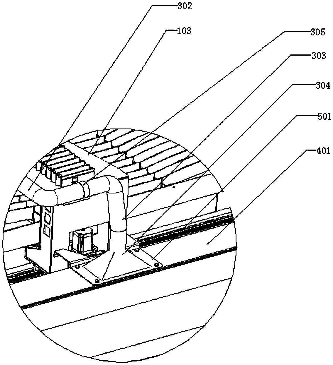
[0023] Further, as Figure 1-2 As shown, the dust collection device 3 includes a first dust collection hood 301, a bellows 302, an L-shaped elbow 303 and a second dust collection hood 304, the first dust collection hood 301 is fixed on the trolley 104 and the first dust collection The collection port of the cover 301 is aligned with the cutting torch 105 to collect smoke and dust. The first integrated cover 301 is connected to one end of the bellows 302 arranged in the Y direction along the gantry 103, and the other end of the ...


PUM


Abstract

The invention discloses a dust removing device dedicated to a computer numerical control cutter. The dust removing device comprises a smoke and dust collecting device, a gas channel, and a dust remover, wherein a collecting port of the smoke and dust collecting device fixed on a trolley is always aligned with a cutting torch, and used for collecting smoke and dust; the collecting port of the smokeand dust collecting device can be driven by the smoke and dust collecting device to move in the Y direction; the smoke and dust collecting device communicates with the gas channel by which the smokeand dust collecting device can be driven to move in the X direction; and the gas channel communicates with the dust remover. By adoption of the dust removing device, the wind speed can be adjusted according to the distance between the cutting torch and the dust remover, thereby avoiding the phenomenon that the wind volume is insufficient and excessive due to the single wind volume form; a first dust collecting hood can run along with the cutting torch in the X direction and the Y direction, and absorb smoke and dust generated from the cutting torch in time, thereby achieving the high smoke anddust capturing efficiency; meanwhile, the dust removing device is reasonable in structural design, high in operability, and capable of solving the smoke and dust disposal problem of the computer numerical control cutter; and after the dust removing device is mounted, the computer numerical control cutter can work in an open-air environment.

Description

technical field [0001] The invention belongs to the technical field of auxiliary equipment for numerical control cutting machines, and in particular relates to a special dust removal device for numerical control cutting machines. The open type collects the smoke and dust generated by the blanking of the board. Background technique [0002] CNC cutting machine is an automatic equipment that uses digital programs to drive the movement of machine tools and drive cutting tools to cut objects. Such as figure 1 As shown, a commonly used CNC cutting machine includes a fuselage 101, a track 102, a gantry 103, a trolley 104 and a cutting torch 105, and a track 102 is fixedly installed on the fuselage 101, and the gantry 103 walks along the track 102 in the X direction. The trolley 104 walks along the gantry 103 in the Y direction, and as the gantry 103 and the trolley 104 move, it drives the cutting torch 105 fixed on the trolley 104 to move in the X and Y directions. The CNC cutt...

Claims


Application Information

Patent Timeline
IPC IPC(8): B08B15/00B23K7/10
CPCB08B15/007B23K7/10
Inventor 肖安金刘瑞洁王贵林陈嘉睿付志伟周庆娇陈晨付志文张文静刘春秀张桂春张新国刘荣战超于杰
Owner 青岛海洋技师学院
Why Eureka
Try Eureka