
Heat energy recycling device

A heat energy recovery and installation room technology, applied in heat pumps, fluid heaters, lighting and heating equipment, etc., can solve the problems of general recovery effect and low heat energy recovery efficiency, and achieve full utilization, improve absorption speed, and increase heat exchange efficiency. Effect

Inactive Publication Date: 2018-11-09
SHENZHEN INST OF ADVANCED TECH CHINESE ACAD OF SCI +1
View PDF7 Cites 0 Cited by
  • Summary
  • Abstract
  • Description
  • Claims
  • Application Information

AI Technical Summary

Problems solved by technology

[0004] In view of this, it is necessary to address the above-mentioned problems and propose a heat energy recovery device to solve the shortcomings of the above-mentioned waste heat recovery device, such as low heat recovery efficiency and general recovery effect

Method used


Image

  • Heat energy recycling device
  • Heat energy recycling device
  • Heat energy recycling device

Examples


Embodiment Construction

[0028] In order to make the purpose, technical solution and advantages of the present invention clearer, the technical solution of the present invention will be further clearly and completely described below in conjunction with the embodiments of the present invention. It should be noted that the described embodiments are only some of the embodiments of the present invention, but not all of the embodiments. Based on the embodiments of the present invention, all other embodiments obtained by persons of ordinary skill in the art without making creative efforts belong to the protection scope of the present invention.

[0029] It should be understood that the orientation or positional relationship indicated by the terms "upper", "lower", "front", "rear", "left", "right" etc. are based on the orientation or positional relationship shown in the drawings, and are only In order to facilitate the description of the present invention and simplify the description, it does not indicate or...


PUM


Abstract

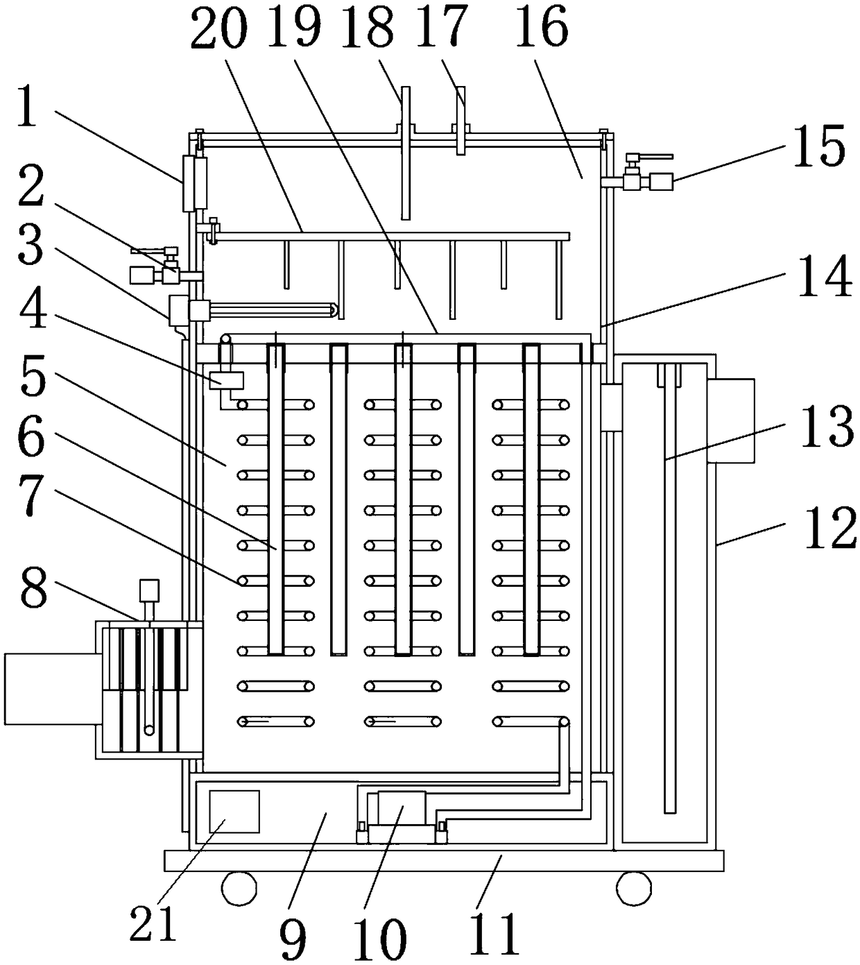
The invention relates to the technical field of environmental protection and energy saving, and particularly discloses a heat energy recycling device. The heat energy recycling device comprises a water tank, a heat energy recycling chamber, an equipment mounting chamber, a main control module, a compressor, a heat release coil, an expansion valve and heat absorbing coils. The water tank, the heatenergy recycling chamber and the equipment mounting chamber are sequentially fixedly mounted and connected; the main control module is electrically connected with the expansion valve and the compressor; the heat absorbing coils and the expansion valve are arranged in the heat energy recycling chamber; the heat release coil is arranged in the water tank; the main control module and the compressor are arranged in the equipment mounting chamber; the output end of the heat release coil is in pipeline connection with the input ends of the heat absorbing coils through the expansion valve; an outputport of the compressor is in pipeline connection with the input end of the heat release coil through a pipeline; and an input port of the compressor is in pipeline connection with output ports of theheat absorbing coils. The absorption speed of heat energy is increased, the heat energy recycling device is suitable for recycling waste heat of high-temperature flue gas which constantly flows at a high speed, the heat exchange efficiency is improved, and the waste heat is fully utilized.

Description

technical field [0001] The invention relates to the technical field of environmental protection and energy saving, in particular to a heat energy recycling device. Background technique [0002] Heat energy recovery is a hot topic in today's society. With the society and the country's emphasis on environmental protection and the promotion of efficient use of energy, various waste heat recovery devices have been invented and created to serve the society, increase economic value, and reduce environmental pollution. pollute. [0003] The waste heat recovery of high-temperature gas generated in boilers and other equipment is of great significance. At present, the waste heat recovery methods for high-temperature gases are passive cold and heat exchange to recover waste heat. Although the purpose of waste heat recovery can be achieved, the recovery effect is general, and some high-speed flow For flue gas, it is obviously inefficient to recover waste heat through passive heat excha...

Claims


Application Information

Patent Timeline
IPC IPC(8): F23J15/06F25B30/02F24H4/02F24H9/20
CPCF23J15/06F24H4/02F24H9/2007F25B30/02Y02E20/30
Inventor 韩汶轩张凤鸣苏闯建陈顺权
Owner SHENZHEN INST OF ADVANCED TECH CHINESE ACAD OF SCI
Learn More