Safety warning device for power equipment

A technology for safety warning and power equipment, applied in electrical transmission signal systems, alarms that rely on interfering short-wavelength radiation, etc. The probability of accidents, the effect of good safety warning, and the effect of saving production costs

Inactive Publication Date: 2018-11-09
黄华生
View PDF0 Cites 3 Cited by
  • Summary
  • Abstract
  • Description
  • Claims
  • Application Information

AI Technical Summary

Problems solved by technology

It mainly includes two categories of power generation equipment and power supply equipment. Power generation equipment is mainly power plant boilers, steam turbines, gas turbines, water turbines, generators, point motors, transformers, etc. Power supply equipment is mainly transmission lines and transformers of various voltage levels. , contactors, etc. At present, warning signs are generally installed around power equipment, with icons printed on them or prompts such as do not approach, used to remind people of the danger here, but most of the existing warning signs do not have For functions such as alarm, it is impossible to remind people to pay attention to safety by voice, the function is single, and the practicability is poor, and the reflective panels with reflective strips are used on the power equipment, relying on reflecting the lights emitted by vehicles to play a warning role
Such a warning effect not only depends on the lighting of the car, if there is no lighting of the car, the warning effect will not be achieved, but also due to the influence of the ambient background light, when the light source is weak, the light intensity reflected by the reflective strip is also weak. It cannot play a warning role, and it is difficult for the driver to judge the distance between the car and the transmission line and related equipment based on the reflected light of the reflective strip

Method used


Image

  • Safety warning device for power equipment
  • Safety warning device for power equipment
  • Safety warning device for power equipment

Examples


Embodiment Construction

[0019] In order to make the technical means, creative features, achievement goals and effects realized by the present invention easy to understand, the present invention will be further described below with reference to the specific embodiments.

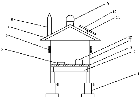
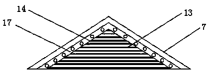
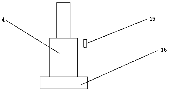
[0020] like Figure 1-3 As shown, a safety warning device for electrical equipment includes a box body 1 and a fixing plate 2. The fixing plate 2 is located inside the box body 1 and can be detachably connected. The upper end of the fixing plate 2 is provided with an infrared sensor 5 and a controller. 12, and the infrared sensor 5 is located on the side of the controller 12, the upper end of the box body 1 is detachably connected with a rainproof cap 7, and one end of the rainproof cap 7 is detachably connected with a warning board 14, and the outer side of the warning board 14 is fixed A light bar 17 is connected, a fluorescent layer 13 is provided on the surface of the warning board 14 , and a warning light 9 is detachably connect...


PUM


Abstract

The invention discloses a safety warning device for power equipment, which comprises a box body and a fixing plate, wherein the fixing plate is located inside the box body and is detachably connected;the upper end of the fixing plate is provided with an infrared sensor and a controller; the infrared sensor is located at one side of the controller; the upper end of the box body is detachably connected with a rainproof cap; one end of the rainproof cap is detachably connected with a warning plate; a lamp strip is fixedly connected outside the warning plate; and a fluorescent layer is arranged on the surface of the warning plate. Through arranging the infrared sensor, a loudspeaker and a warning lamp, when the infrared sensor detects a person approaches the power equipment, signals are transmitted to the controller, the controller controls the warning lamp to light and the loudspeaker to give a sound reminder, and the probability of accidents is effectively reduced; and as the lamp stripis arranged, the warning board can be illuminated effectively at night by the lamp strip, the warning board is clearer, and better safety warning is provided for people passing by and vehicle more conveniently.

Description

technical field [0001] The present invention relates to the technical field of electrical equipment, in particular to a safety warning device for electrical equipment. Background technique [0002] Electricity is an energy source powered by electrical energy. It was invented in the 1870s. The invention and application of electricity set off the second industrialization climax. It has become one of the three scientific and technological revolutions that have occurred in the world since the 18th century in human history. Since then, technology has changed people's lives. The large-scale power system that appeared in the 20th century is one of the most important achievements in the history of human engineering science, and power equipment is a power production and consumption system composed of power generation, transmission, transformation, distribution and consumption. It converts primary energy in nature into electricity through power generation devices, and then supplies e...

Claims


Application Information

Patent Timeline
Patent Type & Authority Applications(China)
IPC IPC(8): G08B13/19G08B7/06
CPCG08B13/19G08B7/06
Inventor 黄华生
Owner 黄华生
Why Eureka
Try Eureka