Work machine
A technology for working machines and working machines, which is applied to mechanical equipment, mechanically driven excavators/dredgers, earthmovers/shovels, etc., and can solve the problem of increased moment of inertia, increased discharge pressure of hydraulic pumps, flow loss, etc. problem, to achieve the effect of energy efficiency and operability
- Summary
- Abstract
- Description
- Claims
- Application Information
AI Technical Summary
Problems solved by technology
Method used
Image
Examples
no. 1 Embodiment approach >
[0029] (1-1) Operating machinery
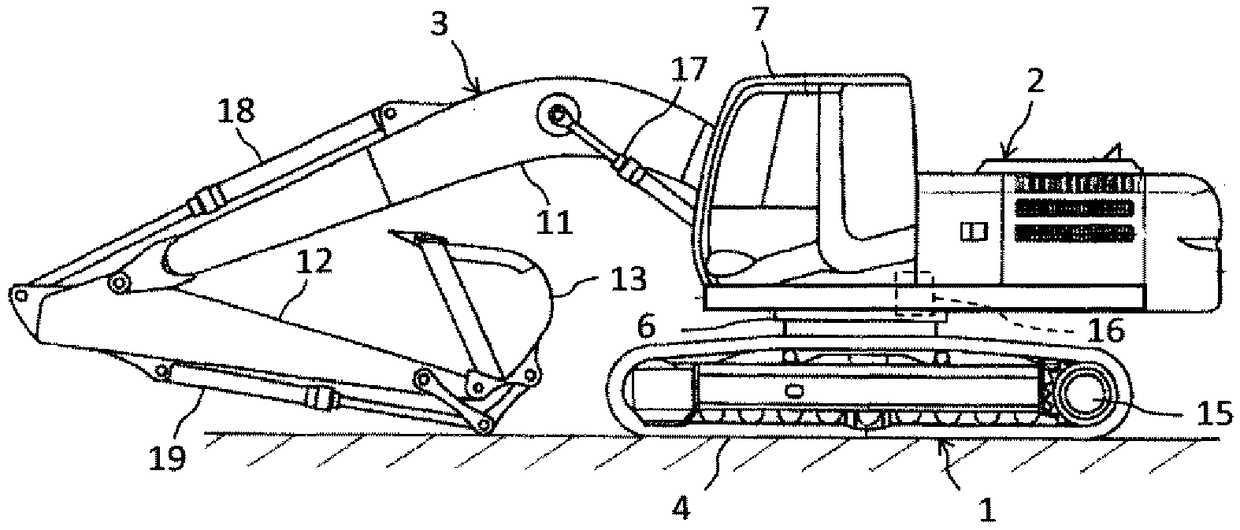
[0030] figure 1 It is a perspective view showing an appearance configuration of a hydraulic excavator as an example of a work machine according to each embodiment of the present invention. In the following instructions, unless otherwise specified, the front of the driver's seat ( figure 1 Middle left) is the front of the body. However, the example of the hydraulic excavator is not intended to limit the applicable object of the present invention, as long as it is a working machine having a revolving body that turns with respect to the base structure, the present invention can also be applied to other types of working machines such as cranes.
[0031] The illustrated hydraulic excavator includes a running body 1 , a revolving body 2 provided on the running body 1 , and a working machine (front working machine) 3 attached to the revolving body 2 . The running body 1 is a base structure of a work machine, and is a crawler traction type running...
no. 2 Embodiment approach >
[0097] (2-1) Composition
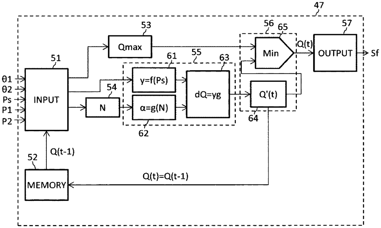
[0098] Figure 7 It is a schematic diagram of the pump controller concerning 2nd Embodiment of this invention. exist Figure 7 In the drawings, the same reference numerals as those in the conventional drawings are assigned to the same elements as those in the first embodiment. The command flow calculation unit 56A of the pump controller 47A of the present embodiment is different from the command flow calculation unit 56 of the pump controller 47 of the first embodiment. The difference between the configuration of the present embodiment and the first embodiment is only in this point, so description of other configurations will be omitted, and the command flow calculation unit 56A will be described below.
[0099] ·Command flow calculation unit
[0100] The command flow calculation unit 56A in the present embodiment includes an operation time calculation unit 66 , a delay time calculation unit 67 , a target flow rate calculation unit 68 , and a minim...
no. 3 Embodiment approach >
[0116] (3-1) Composition
[0117] Figure 9 It is a schematic diagram of the pump controller concerning 3rd Embodiment of this invention. exist Figure 9 In the drawings, the same reference numerals as those in the conventional drawings are assigned to the same elements as those in the first or second embodiment. In the present embodiment, the flow rate increase rate calculation unit 55B and the command flow rate calculation unit 56B of the pump controller 47B are different from the flow rate increase rate calculation unit 55 and the command flow rate calculation unit 56 of the pump controller 47 of the first embodiment. The difference between the configuration of the present embodiment and the first embodiment is only in this point, so the description of other configurations is omitted, and the flow rate increase rate calculation unit 55B and the command flow rate calculation unit 56B will be described below.
[0118] ·Flow rate increase rate calculation unit
[0119] The...
PUM
 Abstract
Description
Claims
Application Information
 - R&D
- Intellectual Property
- Life Sciences
- Materials
- Tech Scout
- Unparalleled Data Quality
- Higher Quality Content
- 60% Fewer Hallucinations
Browse by: Latest US Patents, China's latest patents, Technical Efficacy Thesaurus, Application Domain, Technology Topic, Popular Technical Reports.
© 2025 PatSnap. All rights reserved.Legal|Privacy policy|Modern Slavery Act Transparency Statement|Sitemap|About US| Contact US: help@patsnap.com


