Al technical title is built by PatSnap Al team. It summarizes the technical point description of the patent document.
A technology of diaphragm pumps and diaphragms, which is applied in the direction of pumps, pump components, variable displacement pump components, etc., can solve problems such as difficult control of valve discs, and achieve the effect of simple structure and high sealing performance
Active Publication Date: 2020-03-17
GARDNER DENVER THOMAS
View PDF3 Cites 0 Cited by
Summary
Abstract
Description
Claims
Application Information
AI Technical Summary
This helps you quickly interpret patents by identifying the three key elements:
Problems solved by technology
Method used
Benefits of technology
Problems solved by technology
The problem with these constructions is that it is difficult to control the valve disc, for example in the construction according to DE 10 2012 200 501 A1 by means of a magnetically coupled actuator disc
Method used
Image
Click on the blue label to locate the original text in one second.
Reading with bidirectional positioning of images and text.
Examples
Embodiment Construction
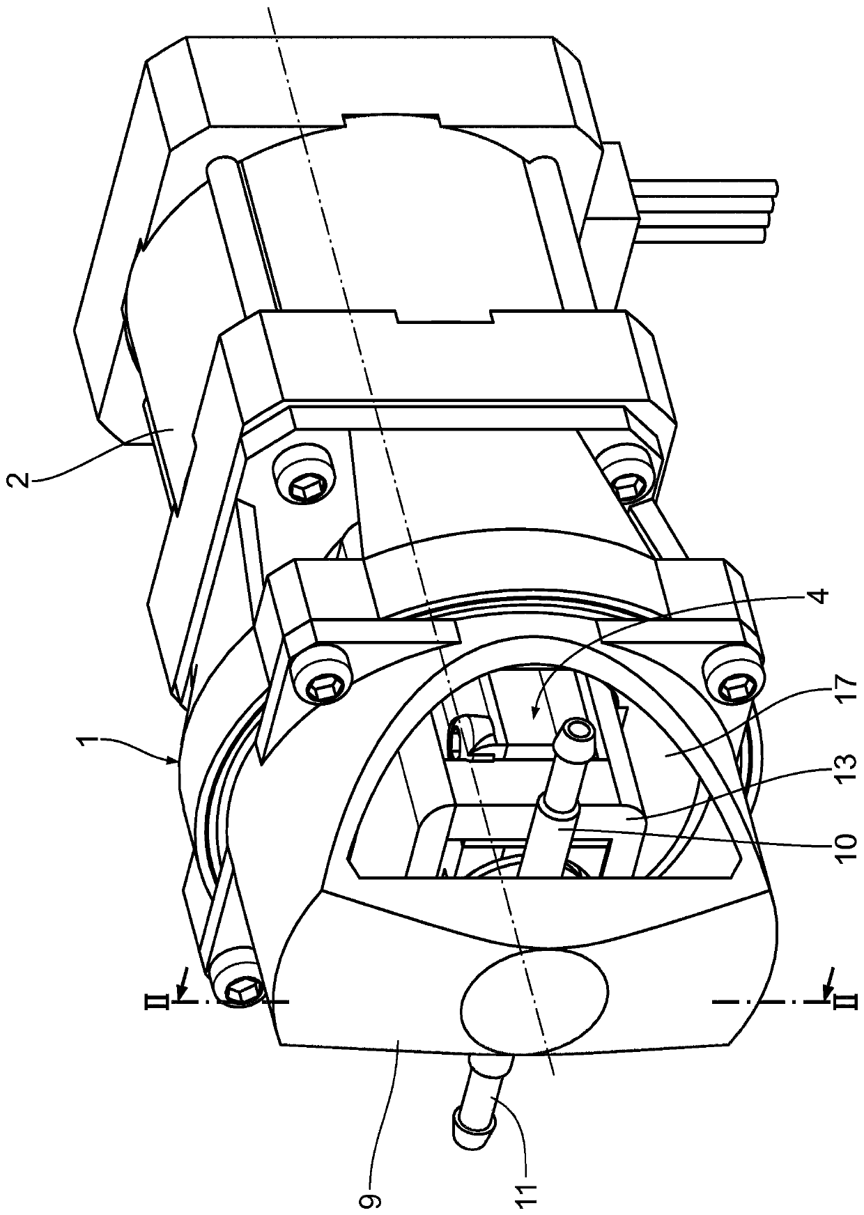
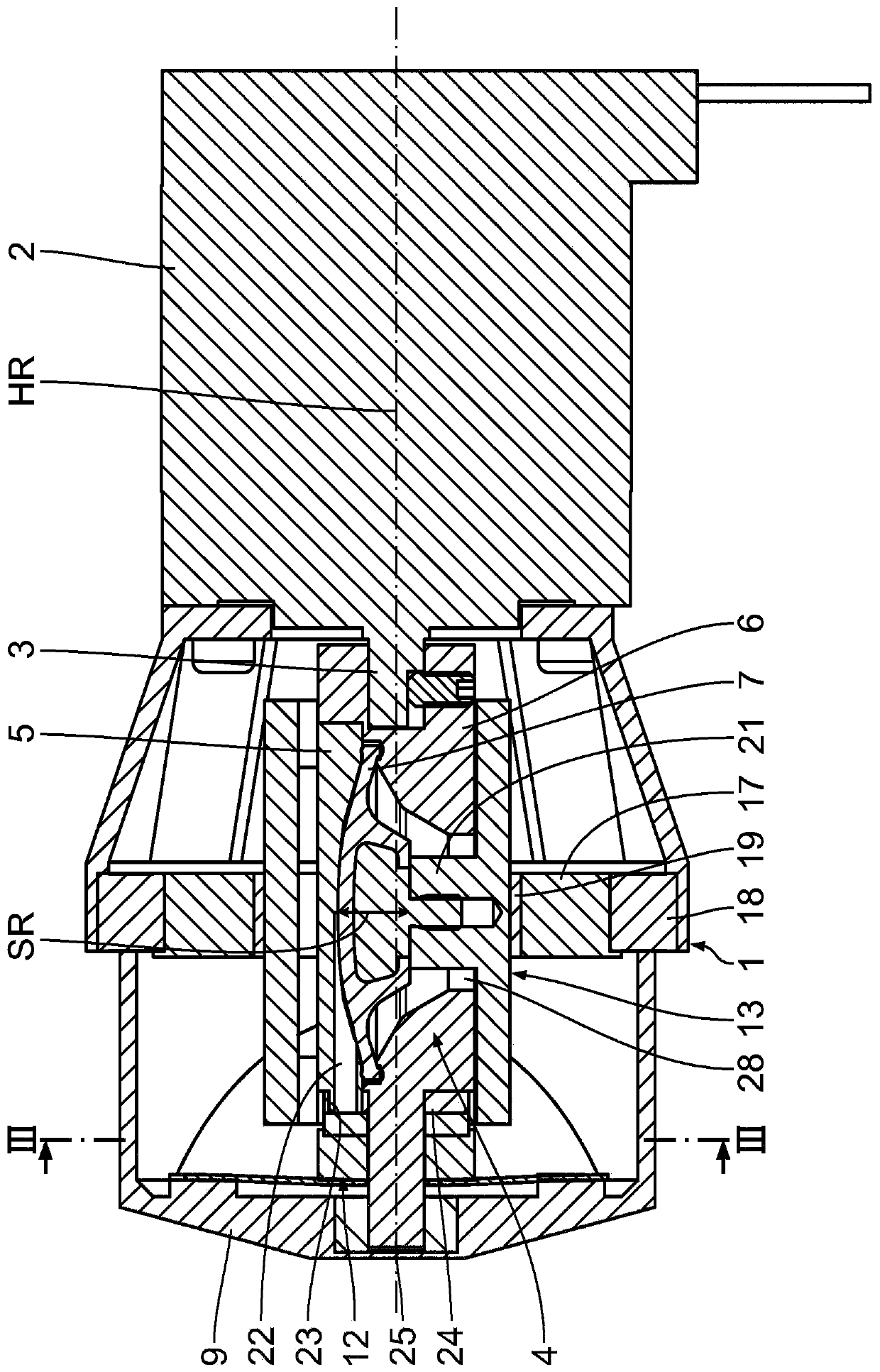
[0051] as from figure 1 and 2 It becomes clear that the illustrated diaphragm pump has a frame-shaped carrier part 1 functioning as a pump housing, on which an electric drive motor 2 is accommodated. exist Figure 4 The drive motor 2 , shown only schematically below, has a drive shaft 3 , which rotates about a main axis of rotation HR. The pump head, generally designated 4, is composed of an upper part 5 and a lower part 6, which delimit a conventional lens-shaped working volume. In this working space, a diaphragm 7 is clamped between the upper part 5 and the lower part 6 , which together with the upper part 5 delimits a pump chamber 8 . The pump head 4 is rotatably mounted in the carrier part 1 in a manner still to be explained in detail and is connected here with the drive shaft 3 in such an orientation that the vibration direction SR of the diaphragm 7 is orthogonal to the main axis of rotation HR of the drive shaft 3 ground pointing.
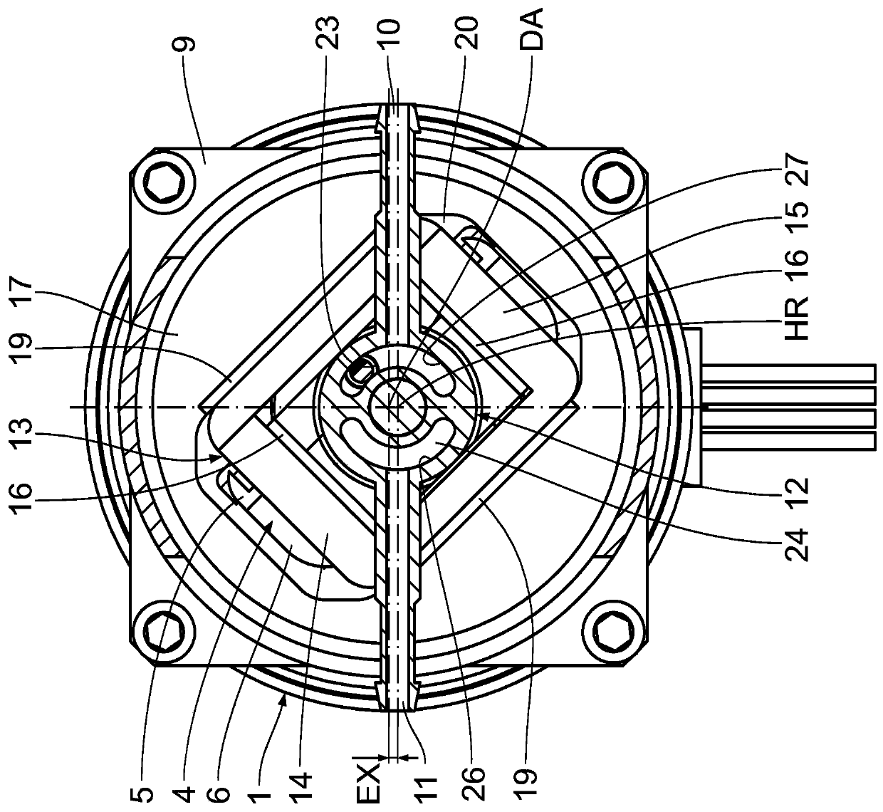
[0052] as from figure 1 and 3 ...
PUM
Abstract
A diaphragm pump comprising: - a carrier part (1), - a drive motor (2) arranged at the carrier part, the drive motor having a drive shaft (3) rotating around a main axis of rotation (HR), - a pump head (4, 4'), the pump head has a pump chamber (8, 8') delimited by a vibratoryly driven diaphragm, and an inlet connection (11) and an outlet connection arranged at the carrier part (1) (10), the connection ends can be connected alternately with the pump chamber (8, 8') in the sense of suction and discharge cycles respectively via exchange valve assemblies (12, 12'), wherein - the pump head (4, 4') is rotatably mounted in the carrier part (1) and connected to the drive shaft (3) in an orientation such that the direction of vibration (SR) of the diaphragm (7, 7') is aligned with the direction of vibration of the drive shaft (3) The main axis of rotation (HR) is directed orthogonally, - a drive transmission element (13, 13') is provided for the diaphragm (7, 7') which: = on the one hand at the side of the diaphragm (7, 7') is mounted deflectably on the pump head (4, 4') in the direction of vibration (SR) and connected to the diaphragm (7, 7') in a driving motion via a coupling element (21, 21'), and = The drive transmission element is displaceably guided orthogonally to the vibration direction (SR) of the diaphragm (7, 7') in a bearing disc (17) mounted eccentrically rotatably relative to the main axis of rotation (HR) as follows , so that = the rotation of the pump head (4, 4') caused by the drive shaft (3) and the drive transmission element (13, 13') relative to the pump head (4, 4') due to eccentricity And with respect to the offset of the bearing plate (17), the rotation of the drive transmission element (13, 13') caused by the pump head (4, 4') is synchronized, and the drive transmission element (13, 13') is coupled through it Elements (21, 21') generate an oscillating movement of the diaphragm (7, 7') in the pump chamber (8, 8'), and - by rotation of the pump head (4, 4') will be arranged in the The pump medium line (22) in the pump head is alternately connected to the inlet connection (11) or the outlet connection (10).
Description
[0001] This patent application claims priority from German patent application DE 10 2016 204 487.7, the content of which is hereby incorporated by reference. technical field [0002] The invention relates to a diaphragm pump having the features given in the preamble of claim 1 . Background technique [0003] Conventional diaphragm pumps have a pump housing substantially in the form of a carrier part and a drive motor held on the pump housing with a drive shaft rotating about a main axis of rotation. Arranged in the pump head is a pump mechanism in the form of a diaphragm which delimits a pump chamber and is driven vibratingly by a drive shaft of an electric motor via a suitable eccentric drive. [0004] An inlet connection and an outlet connection are provided on the carrier part, which can be alternately connected to the pump chamber in each case via a switching valve arrangement in the sense of a suction and discharge cycle. [0005] In conventional diaphragm pumps, this ...
Claims
Application Information
Patent Timeline
Application Date:The date an application was filed.
Publication Date:The date a patent or application was officially published.
First Publication Date:The earliest publication date of a patent with the same application number.
Issue Date:Publication date of the patent grant document.
PCT Entry Date:The Entry date of PCT National Phase.
Estimated Expiry Date:The statutory expiry date of a patent right according to the Patent Law, and it is the longest term of protection that the patent right can achieve without the termination of the patent right due to other reasons(Term extension factor has been taken into account ).
Invalid Date:Actual expiry date is based on effective date or publication date of legal transaction data of invalid patent.