

Motorized valve and refrigeration cycle system
A technology of electric valves and spools, applied in the direction of fluid circulation arrangements, valve details, valve devices, etc., can solve problems such as large spool loads, and achieve good workability
- Summary
- Abstract
- Description
- Claims
- Application Information
AI Technical Summary
Problems solved by technology
Method used
Image

Examples
Embodiment Construction
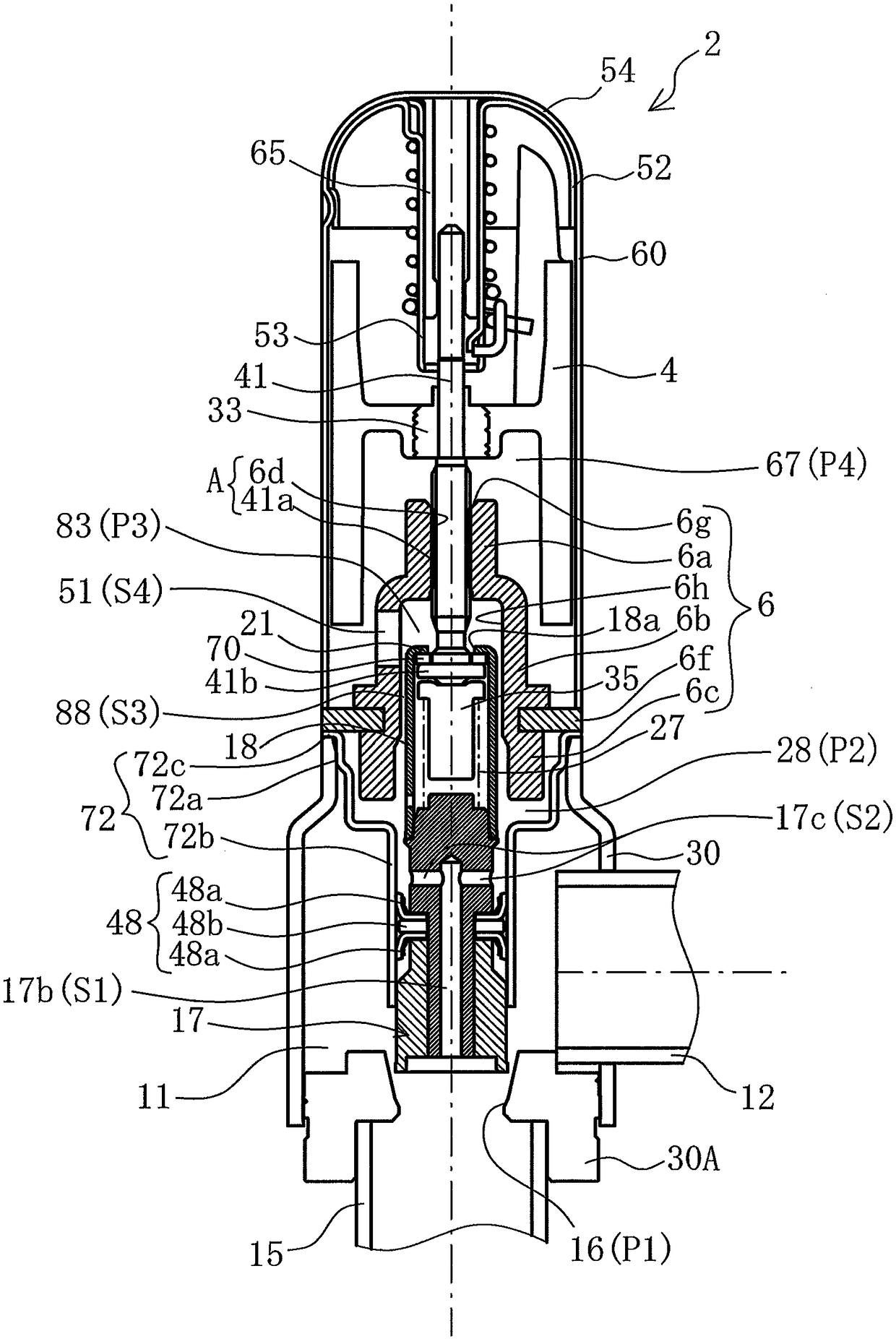
[0034] Hereinafter, an electric valve according to an embodiment of the present invention will be described with reference to the drawings. figure 1 It is a sectional view showing the electric valve 2 of the embodiment. Also, in this specification, in figure 1 The state specifies "up" or "down". That is, the rotor 4 is located above the spool 17 . In addition, in this specification, the valve seat member 30A is arranged at the bottom of the electric valve 2 . Furthermore, the valve body 17 is located near the valve seat member 30A arranged below, and the valve shaft holder 6 is located at a position farther from the valve seat member 30A than the valve body 17 .
[0035] In this electric valve 2 , a valve main body 30 is integrally connected by welding or the like below the opening side of a cylindrical cup-shaped housing 60 made of a non-magnetic material.
[0036] Here, the valve main body 30 is a press-formed product produced by press working of a stainless steel shee...
PUM
 Abstract
Description
Claims
Application Information