Corneal sphere tracking for generating an eye model

An eye tracking, eye technology, applied in the field of eye tracking, can solve the problem of not providing eye tracking accuracy

Active Publication Date: 2018-11-09
CTRL LABS CORP
View PDF5 Cites 14 Cited by
  • Summary
  • Abstract
  • Description
  • Claims
  • Application Information

AI Technical Summary

Problems solved by technology

These conventional systems do not provide suffic...

Method used


Image

  • Corneal sphere tracking for generating an eye model
  • Corneal sphere tracking for generating an eye model
  • Corneal sphere tracking for generating an eye model

Examples


Embodiment Construction

[0045] System Overview

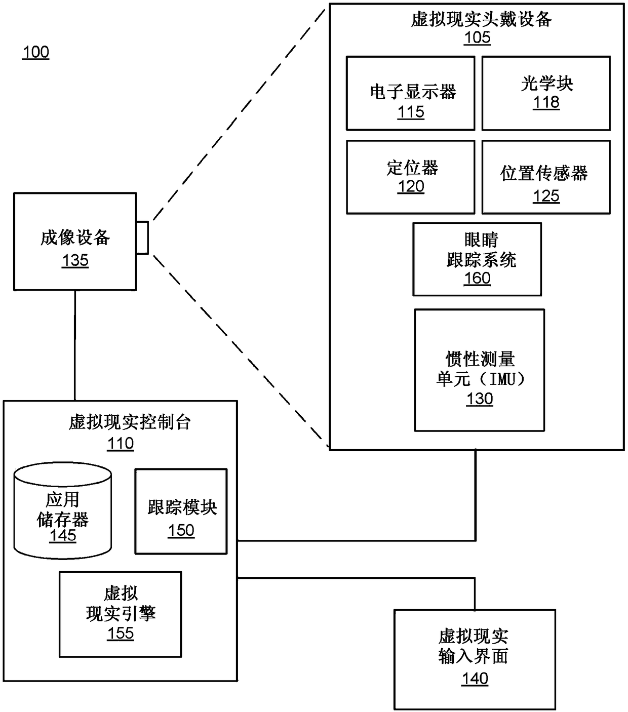
[0046] figure 1 is a block diagram of the VR system environment 100 in which the VR console 110 operates. figure 1 The illustrated system environment 100 includes a VR headset 105 , an imaging device 135 , and a VR input interface 140 each coupled to a VR console 110 . although figure 1 An example system 100 is shown including a VR headset 105 , an imaging device 135 , and a VR input interface 140 , but in other implementations any number of these components may be included in the system 100 . For example, there may be multiple VR headsets 105, each VR headset 105 having an associated VR input interface 140 and being monitored by one or more imaging devices 135, wherein each VR headset 105, VR input interface 140 Interface 140 and imaging device 135 are in communication with VR console 110 . In alternative configurations, different and / or additional components may be included in the system environment 100 .

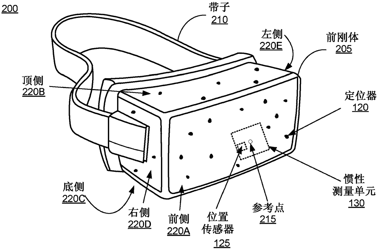
[0047] The VR headset 105 is an HMD th...


PUM


Abstract

A head mounted display (HMD) comprises an eye tracking system configured to enable eye tracking using light. The eye tracking system comprises two or more illumination sources positioned relative to one another and an optical detector for each eye. The optical detector is configured to capture images of the illumination sources using reflections from the eye. The system gathers data as the user views various objects in the HMD. The system determines a shape of the eye by determining one or more of a pupil shape, a foveal offset, and a corneal radius in three-dimensional space. The shape of theeye is used determine a three-dimensional position of the user's eye as well as a gaze direction.

Description

technical field [0001] The present disclosure relates generally to eye tracking, and in particular to corneal ball tracking for generating eye models. Background technique [0002] Eye tracking is an important feature for head mounted display (HMD) systems, including those used in virtual reality (VR) applications. Conventional tracking systems track features of the human eye and are generally limited by the quality of the optical path. These conventional systems do not provide sufficient accuracy required for eye tracking in HMD systems. Contents of the invention [0003] An eye tracking system for generating and calibrating eye models is disclosed. Eye tracking systems may be used in VR system environments or other system environments such as augmented reality (AR) systems. An eye tracking system includes at least two illumination sources and an optical sensor for modeling each eye. The optical sensor and at least two illumination sources are positioned relative to e...

Claims


Application Information

Patent Timeline
IPC IPC(8): G02B27/00G02B27/01
CPCA61B3/0025A61B3/113G02B27/00G02B27/01G02B27/017G02B2027/0138G02B2027/0187G02B27/0172G02B27/0093G02B27/0179
Inventor 沃伦·安德鲁·亨特罗伯特·达勒·卡文
Owner CTRL LABS CORP
Why Eureka
Try Eureka