Eureka AIR delivers breakthrough ideas for toughest innovation challenges, trusted by R&D personnel around the world.

Tool-setting adjusting assembly for cutting moving cutter and hay cutter with assembly

A technology of assembly and guillotine cutting, applied in agricultural machinery and tools, cutting equipment, applications, etc., can solve the high time cost and labor cost of knife adjustment, difficulty in mastering the operation skills of knife adjustment and knife setting, and affect the utilization rate of hay cutter and other problems, to achieve the effect of easy control of the knife setting gap, improve the efficiency and quality of hay cutting operation, and reduce the labor load

Pending Publication Date: 2018-11-13
刘全 +1
View PDF4 Cites 1 Cited by
  • Summary
  • Abstract
  • Description
  • Claims
  • Application Information

AI Technical Summary

Problems solved by technology

The advantage of this method is that it is suitable for single-edged movable knives and double-edged movable knives. The disadvantages are that it takes a long time to set the knife and requires a lot of labor. , Even for a production company, experienced technicians are needed to complete the knife setting adjustment. Therefore, the time cost and labor cost of knife adjustment after the moving knife is worn are high; Move and adjust in the direction of the fixed knife, or tap the knife body of the moving knife, and fine-tune away from the direction of the fixed knife until it meets the clearance requirements of the knife
However, the single-edged moving knife is only half of the service life of the double-edged moving knife, which increases user costs, affects the utilization rate of the hay cutter, and has low user acceptance
[0004] The above two methods of tool setting have greater damage to the tool body

Method used


Image

  • Tool-setting adjusting assembly for cutting moving cutter and hay cutter with assembly
  • Tool-setting adjusting assembly for cutting moving cutter and hay cutter with assembly
  • Tool-setting adjusting assembly for cutting moving cutter and hay cutter with assembly

Examples


Embodiment Construction

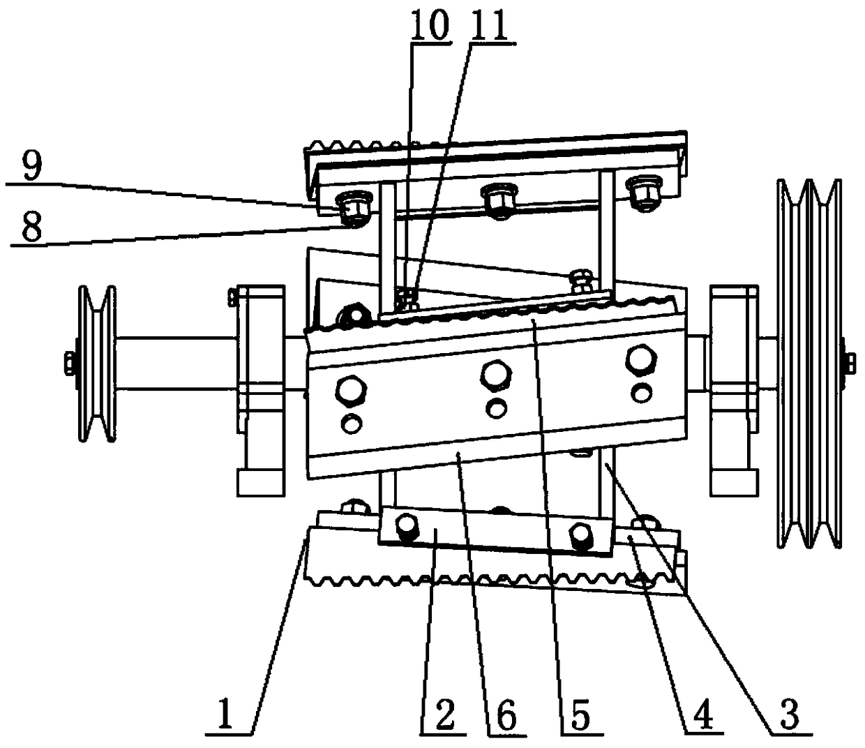
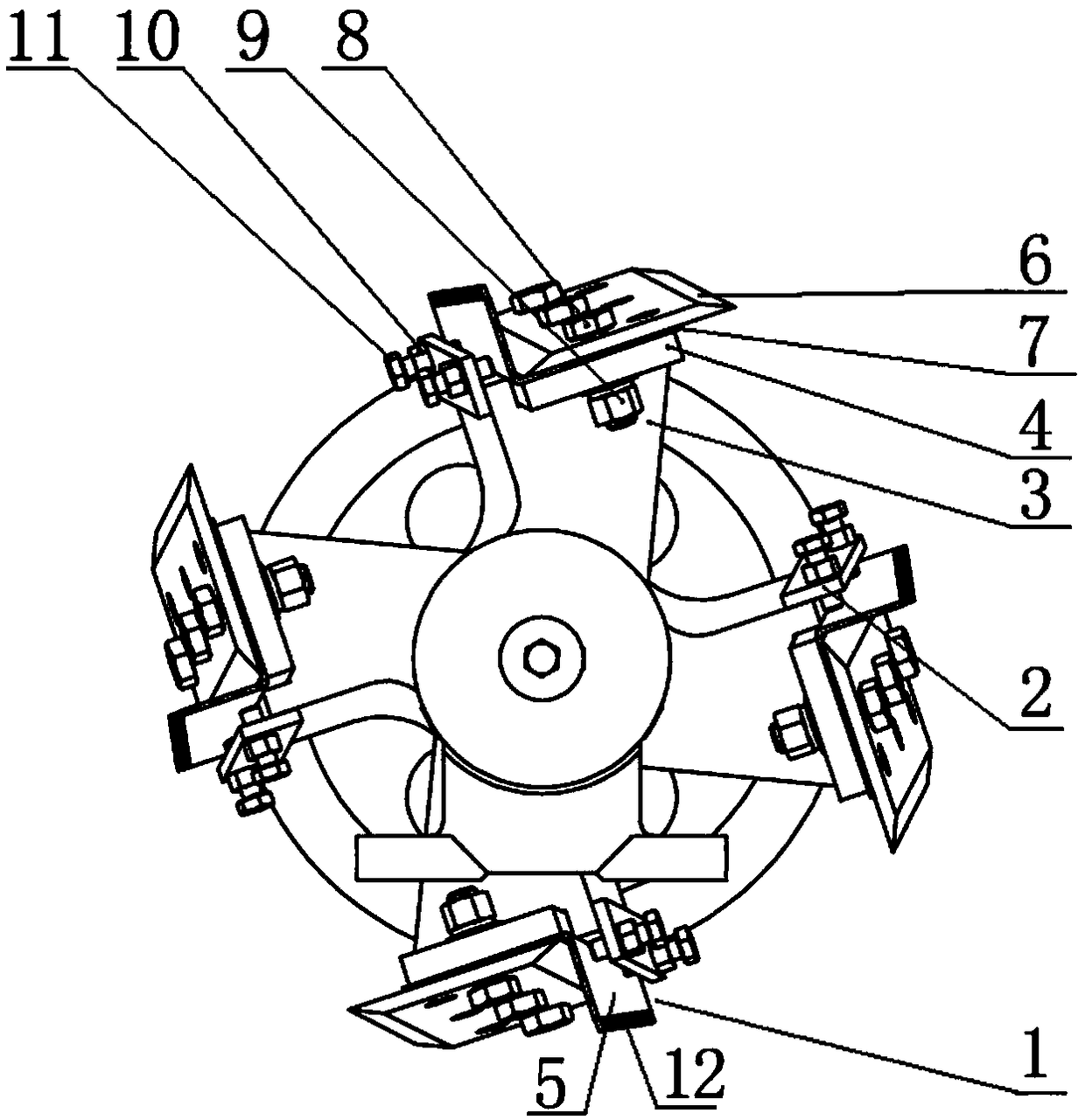
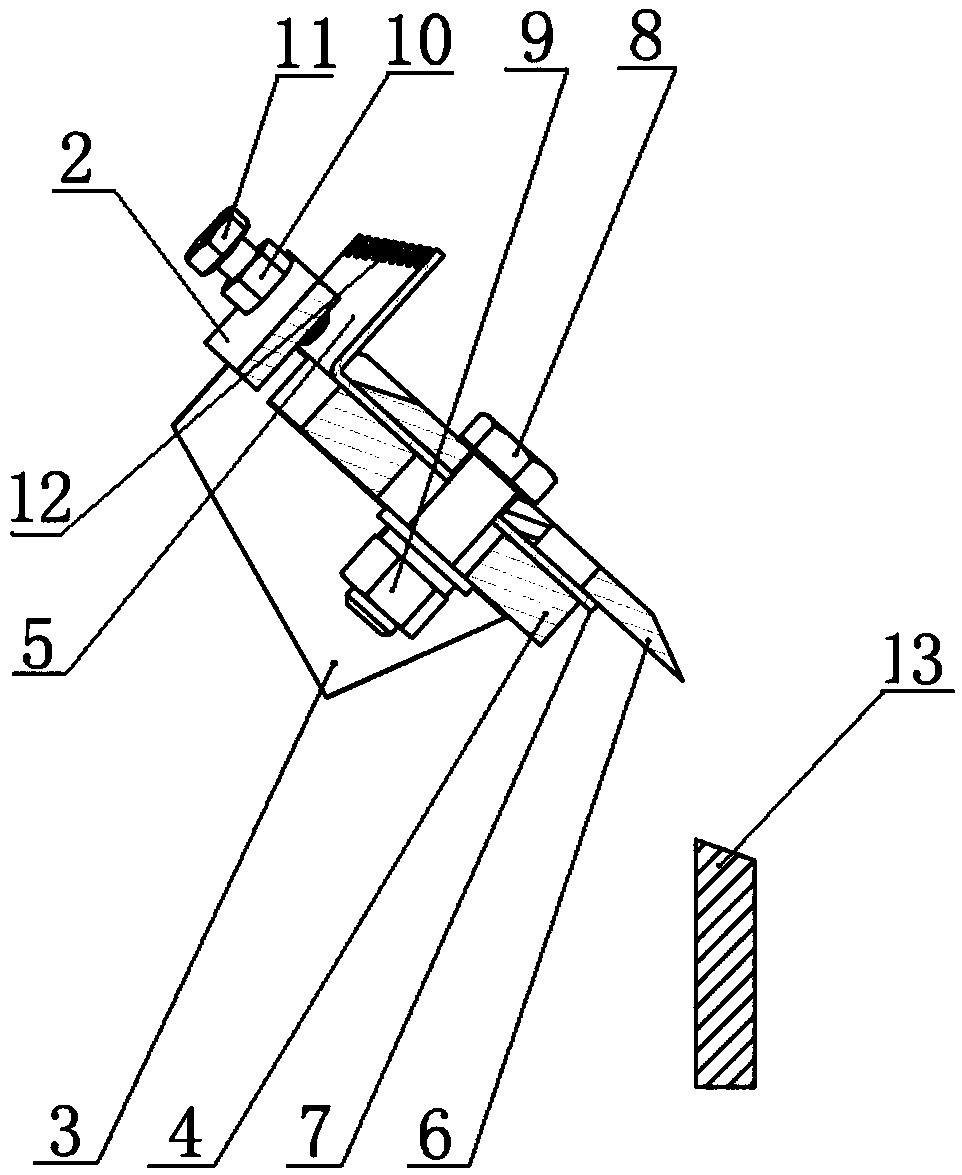
[0014] The utility model relates to a hay cutter provided with a knife-setting adjustment assembly for a guillotine cutter. As shown in the figure is the cutting knife setting adjustment assembly of this mower.

[0015] This guillotine cutter moving knife setting adjustment assembly includes a moving knife 6 and a rotary knife rest 3. In this embodiment, the rotary knife rest 3 is driven by a motor and a belt transmission mechanism for rotary operation.

[0016] Described moving knife 6 is double-edged moving knife, when one side blade wears seriously, can turn 180 °, use the other side blade. The movable knife 6 is fixedly installed on the knife seat evenly distributed on the circumference of the rotary knife rest 3 by the fixed bolt 8 and the fixed nut 9. The knife seat is adjusted by the knife seat plate 4 and the vertical knife seat plate 4 at the rear of the knife seat plate 4. Knife seat 2 is formed. This assembly also includes a knife adjustment angle frame 1, the kni...


PUM


Abstract

The invention provides a tool-setting adjusting assembly for a cutting moving cutter and a hay cutter with an assembly. The tool-setting adjusting assembly comprises a moving cutter and a rotary cutter rest, cutter holders uniformly distributed on the periphery of the rotary cutter rest comprise a cutter holder plate and a cutter adjusting seat, and the cutter adjusting seat is arranged at the rear part of the cutter holder plate and is vertical to the cutter holder plate; a cutter support plate of the cutter adjusting angle frame is arranged between the moving cutter and the cutter seat plate; a fixed bolt penetrates through a moving cutter bolt hole, a cutter support plate bolt hole and a cutter seat plate long hole and is matched with a nut so as to fasten the moving cutter; and a cutter adjusting bolt and a nut are mounted on the cutter adjusting seat, and the cutter adjusting bolt acts on the surface of a vertical plate of the cutter adjusting angle frame. According to the technical scheme, the convenient, rapid and accurate tool-setting operation is realized without damaging a cutter body, and the technical problems perplexing enterprises and users that the repeated tool-setting operation is tedious after a cutting edge is absorbed and overhauled, the labor amount is large, the cutter body is greatly damaged, the operation time is long, and the tool-setting operation generally needs to be finished by a professional with rich experiences are solved.

Description

technical field [0001] This patent application relates to rotary guillotine cutting equipment in agricultural operation machinery, such as hay cutters, hay cutter grinders, guillotine cutters and silk kneading machines, etc., and especially relates to the moving knife cutting and knife setting adjustment mechanism. Background technique [0002] For rotary guillotine cutting agricultural machinery, the most critical thing is the gap between the moving knife and the fixed knife. Good guillotine cutting has low energy consumption, low blade wear, high operating efficiency and high cutting quality; on the contrary, it is prone to machine jams, stuffy machines, and damage to the motor. Even if it can barely run, the quality of guillotine cutting cannot be guaranteed, and High energy consumption, severe blade wear, low operating efficiency, and shortened service life of the whole machine. [0003] The current drum-type hay cutter type agricultural machinery mainly adopts the foll...

Claims


Application Information

Patent Timeline
Patent Type & Authority Applications(China)
IPC IPC(8): A01F29/00A01F29/09
CPCA01F29/00A01F29/09
Inventor 刘全徐文军
Owner 刘全
Why Eureka
Eureka Blog
Learn More