Cleaning head for dust collection tool

A technology of cleaning heads and tools, applied in the field of cleaning heads, can solve the problems of reducing the number of replacement cleaning heads, poor cleaning effect of stubborn stains, and reducing secondary pollution of air, so as to reduce the number of replacement cleaning heads and facilitate Enter the dust suction duct and reduce the effect of secondary pollution

Inactive Publication Date: 2018-11-13
阳珉
View PDF0 Cites 5 Cited by
  • Summary
  • Abstract
  • Description
  • Claims
  • Application Information

AI Technical Summary

Problems solved by technology

[0006] The beneficial effect of the scheme mainly lies in that when the cleaning head is working in rotation, the bottom surface of the cleaning body arranged at intervals in the circumferential direction and protruding downward can wipe the surface to be cleaned, and the cleaning body extending radially has the shortest air inlet distance and relatively short distance. Small air intake resistance, the side edge of the cleaning body has a scraping effect on the surface to be cleaned, which can overcome the shortcomings of ordinary circular rotary cleaning heads that can only wipe with the bottom plane, and the cleaning effect on stubborn stains is not good, and the cleaning head itself When it is dirty, it can also collect and push the dirt, reducing the number of times to replace the cleaning head; the cleaning body is made of flexible wipes, which can be used wet and dry, so that the dust adheres to the cleaning body, reducing indoor air pollution caused by fine dust flocs. Secondary pollution; the semi-enclosed dust suction duct formed by the space between the adjacent cleaning body, the upper cover, and the surface to be cleaned is in a rotating state during operation, which increases the range of suction and has a smaller air intake area , Only a small suction force can suck the dirt into the suction hole; the sweeping and dragging functions can be realized through the cleaning head, realizing the integration of sweeping, dragging and suction

Method used


Image

  • Cleaning head for dust collection tool
  • Cleaning head for dust collection tool
  • Cleaning head for dust collection tool

Examples


Embodiment 1

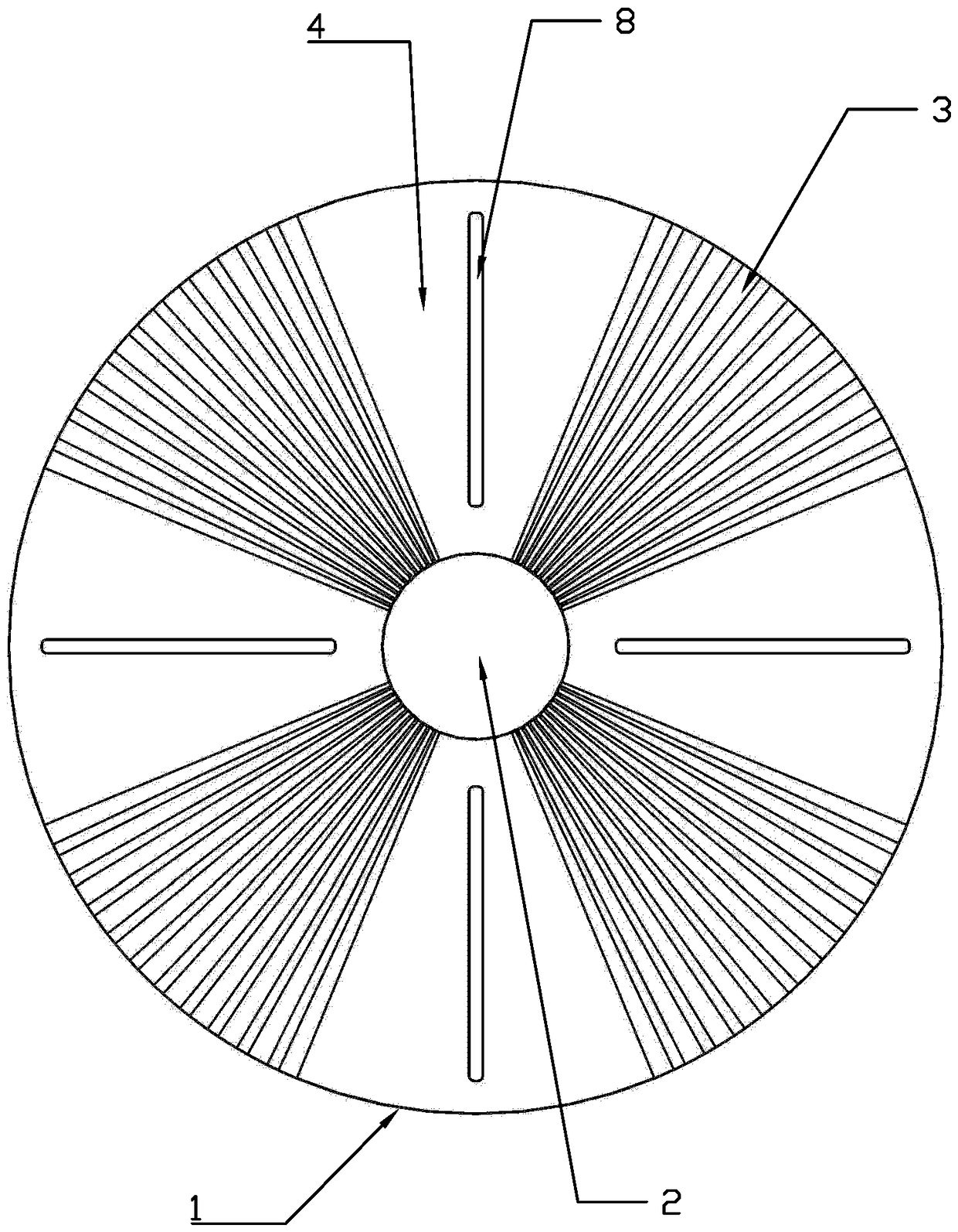
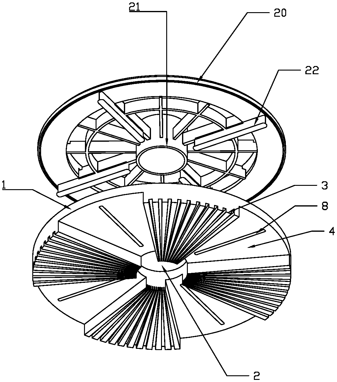
[0022] Embodiment 1: as figure 1 , figure 2 As shown, the cleaning head includes an upper cover 1, the center of the upper cover 1 is provided with a dust suction hole 2, and the lower part of the upper cover 1 is centered on the dust suction hole 2 and is provided with a plurality of radially extending and downward Raised cleaning body 3; in the present embodiment, the lower surface of the cleaning body 3 is preferably fan-shaped, and the cleaning body 3 is made of a flexible wiping material, and the flexible wiping material can be collodion, sponge, fiber fabric or people in the industry Known other flexible materials that can be used for wiping and sweeping the ground, in the present embodiment, upper cover 1 and cleaning body 3 are preferably polyvinyl alcohol collodion foaming materials, and the lower surface of cleaning body 3 is provided with alveolus, adopts mold Integral molding, the upper cover 1 is provided with an installation groove 8 for installation, and the i...

Embodiment 2

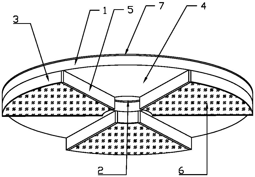
[0023] Embodiment 2: as image 3 As shown, the cleaning head includes an upper cover 1, the center of the upper cover 1 is provided with a dust suction hole 2, and the upper surface of the upper cover 1 is glued or sewn with a Velcro 7, and the Velcro 7 is attached to the bottom of the host during installation. The velcro provided under the installed mounting plate fits together; under the upper cover 1, a plurality of radially extending and downwardly protruding cleaning bodies 3 are arranged at circumferential intervals around the dust suction hole 2, and the cleaning bodies 3 and The upper cover 1 is made of sponge, and the cleaning body 3 and the upper cover 1 can be molded as a whole, or the cleaning body 3 and the upper cover 1 can be glued together, and the lower surface of the cleaning body 3 is glued or sewn with a wiping cloth 6 , on the side of the edge of the cleaning body 3, a scraper 5 is glued, and the scraper 5 can be made of rubber, silica gel or other materia...

Embodiment 3

[0024] Embodiment 3: as Figure 4 As shown, the cleaning head includes an upper cover 1, the center of the upper cover 1 is provided with a dust suction hole 2, and the upper surface of the upper cover 1 is glued or sewn with a Velcro 7, and the Velcro 7 is attached to the bottom of the host during installation. The velcro provided under the installed mounting plate fits together; under the upper cover 1, a plurality of radially extending and downwardly protruding cleaning bodies 3 are arranged at circumferential intervals around the dust suction hole 2, and the cleaning bodies 3 and The upper cover 1 is made of sponge, and the cleaning body 3 and the upper cover 1 can be molded as a whole, or the cleaning body 3 and the upper cover 1 can be glued together, and the lower surface of the cleaning body 3 is glued or sewn with a wiping cloth 6 The part of the lower surface of the cleaning body 3 near the outside has an upwardly tilted slope or curved surface; the lower surface of ...


PUM


Abstract

The invention discloses a cleaning head for a dust collection tool. The cleaning head comprises an upper cover, wherein a dust collection hole is formed in the center of the upper cover, a plurality of cleaning bodies extending along the radial direction and protruding downwards are circumferentially arranged below the lower cover at intervals by taking the dust collection hole as a center and aremade from flexible rubbing materials, the lower surfaces of the cleaning bodies are in contact with a cleaned surface, the cleaned surface is rotatably wiped, and a dust collection air channel for absorbing dirt into the dust collection hole is formed among the adjacent cleaning bodies, the upper cover and the cleaned surface. The cleaning head can be applied to cleaning tools such as an electricmop, a dust collector and a sweeping robot, so that the sweeping, mopping and absorption operations can be integrated, and the secondary pollution of indoor air in the cleaning process is reduced; and the cleaning head has the characteristics of good cleaning effect and high cleaning efficiency.

Description

technical field [0001] The invention relates to the field of cleaning tools, in particular to a cleaning head used for cleaning tools such as a vacuum cleaner or a sweeper with a dust suction function, a sweeping robot, and an electric rotary mop. Background technique [0002] In the prior art, tools that use the cleaning head to rotate for cleaning have been widely used, such as vacuum cleaners with rotating brushes, sweepers, sweeping robots, etc., but vacuum cleaners with rotating brushes can only vacuum or sweep the floor, and cannot mop It is impossible to remove dirt and sewage on the ground, and the suction can only act on the vicinity of the suction port, and the hair is easily entangled on the bristles and even the rotating shaft. In addition, the bristles that rotate and hit the ground are likely to cause dust to fly and float in the air, resulting in indoor air pollution. secondary pollution. [0003] In addition, in the electric rotary mop, a round mop is genera...

Claims


Application Information

Patent Timeline
IPC IPC(8): A47L9/04A47L11/40
CPCA47L9/0472A47L11/4038
Inventor 阳珉
Owner 阳珉
Why Eureka
Try Eureka