Medicinal CT guiding and puncturing positioning device

A technology of locator and backing plate, which is applied in the medical field, can solve the problems of doctor's puncture position deviation, inability to achieve fixation effect, patient pain and injury, etc., so as to reduce work difficulty, achieve good fixation effect, and avoid affecting CT work Effect

Inactive Publication Date: 2018-11-13
FOSHAN JIAOTU TECH CO LTD
View PDF1 Cites 0 Cited by
  • Summary
  • Abstract
  • Description
  • Claims
  • Application Information

AI Technical Summary

Problems solved by technology

[0002] In this study, CT-guided biopsy is a commonly used method for the diagnosis and treatment of lung diseases. The diagnosis of some lung lesions requires the use of puncture to perform sampling and biopsy on the lesion in order to achieve the purpose of diagnosis; at present, CT-guided biopsy in the prior art The puncture is to find out the best level of puncture and the position of the needle through the CT scan image, and then mark the injection point on the patient's body surface, such as the patent application number "201620394782.6", which includes a CT examination table and a sliding set on the side of the CT examination table The positioning device is used to locate the direction and position of the puncture. A puncture needle is installed on the positioning device. Although the patent achieves positioning for the puncture, in this patent, the positioning device is always connected with the CT bed. When the patient does not need to puncture In this case, the device hinders the normal work, and the patent cannot achieve a good fixation effect after positioning the puncture site, and it is very easy to make the position just positioned shift, resulting in a failure of positioning. At this time, it is easy It causes the doctor's puncture position to deviate, causing pain and injury to the patient, so the existing technology cannot meet the needs of people today for a medical CT-guided puncture positioner that is easy to disassemble, avoid affecting CT work, and has a good fixation effect.

Method used


Image

  • Medicinal CT guiding and puncturing positioning device
  • Medicinal CT guiding and puncturing positioning device
  • Medicinal CT guiding and puncturing positioning device

Examples


Embodiment Construction

[0015] The following will clearly and completely describe the technical solutions in the embodiments of the present invention with reference to the accompanying drawings in the embodiments of the present invention. Obviously, the described embodiments are only some, not all, embodiments of the present invention. Based on the embodiments of the present invention, all other embodiments obtained by persons of ordinary skill in the art without making creative efforts belong to the protection scope of the present invention.

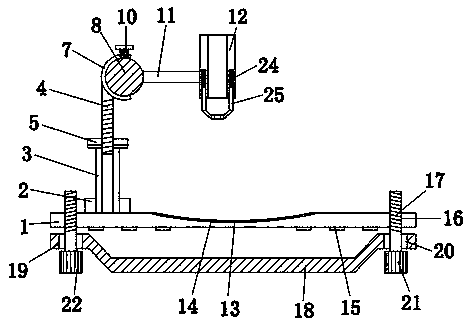
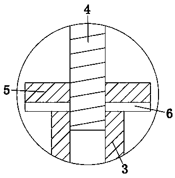
[0016] see Figure 1-4 , the present invention provides a technical solution: a medical CT-guided puncture positioner, including a backing plate 1, a groove 13 is provided in the center of the top of the backing plate 1, the groove 13 prevents the patient’s body from shifting, and the top of the backing plate 1 is left The first bearing 2 is fixedly connected to the side, and the inner wall of the first bearing 2 is fixedly connected with a threaded cylinder 3...


PUM


Abstract

The invention discloses a medicinal CT guiding and puncturing positioning device. The device comprises a base plate, a groove is formed in the center of the top of the base plate, the outer wall of afirst threaded rod is in threaded connection with the inner wall of a threaded barrel, a nut is arranged on the outer wall of the first threaded rod, the bottom of a rubber ring and the top of the threaded barrel are attached, and a hemisphere is fixed on the right side of the top of the first threaded rod. The medicinal CT guiding and puncturing positioning device not only realizes guiding at theearly stage when a patient needs to be punctured, convenient detaching and disease condition detection for part of patients, but also realizes a good positioning effect on a sleeve, and it is avoidedthat after positioning, positions deviate. In this way, the medicinal CT guiding and puncturing positioning device can completely meet the demand of people for the medicinal CT guiding and puncturingpositioning device which is convenient to detach and good in fixing effect nowdays, and avoids influences on CT work.

Description

technical field [0001] The invention relates to the field of medical technology, in particular to a medical CT-guided puncture positioner. Background technique [0002] In this study, CT-guided biopsy is a commonly used method for the diagnosis and treatment of lung diseases. The diagnosis of some lung lesions requires the use of puncture to perform sampling and biopsy on the lesion in order to achieve the purpose of diagnosis; at present, CT-guided biopsy in the prior art The puncture is to find out the best level of puncture and the position of the needle through the CT scan image, and then mark the injection point on the patient's body surface, such as the patent application number "201620394782.6", which includes a CT examination table and a sliding set on the side of the CT examination table The positioning device is used to locate the direction and position of the puncture. A puncture needle is installed on the positioning device. Although the patent achieves positioni...

Claims


Application Information

Patent Timeline
Patent Type & Authority Applications(China)
IPC IPC(8): A61B17/34A61B90/00
CPCA61B17/3403A61B90/37A61B90/39A61B2090/3762
Inventor 邓建强
Owner FOSHAN JIAOTU TECH CO LTD
Why Eureka
Try Eureka