
Medical waste compression treatment device

A compression treatment device, medical waste technology, applied in the direction of solid waste removal, press, combustion type, etc., can solve the problems of increased transportation cost, pollutant leakage, large volume of medical waste, etc., to improve waste treatment efficiency, improve Combustion efficiency, the effect of preventing the concentration of waste

Inactive Publication Date: 2018-11-13
唐莉
View PDF9 Cites 3 Cited by
  • Summary
  • Abstract
  • Description
  • Claims
  • Application Information

AI Technical Summary

Problems solved by technology

[0003] Due to the increase in the number of patients, the amount of medical waste generated during the diagnosis, treatment, and nursing activities of patients is also increasing. At present, there are big problems in the treatment of medical waste. The treatment of medical waste is not up to standard. Due to the large volume of medical waste, the transportation is cumbersome and difficult, and the transportation equipment is simple, which will not only leak pollutants, increase the risk of infection, but also increase transportation costs

Method used


Image

  • Medical waste compression treatment device
  • Medical waste compression treatment device
  • Medical waste compression treatment device

Examples


Embodiment Construction

[0024] Below in conjunction with accompanying drawing and embodiment, further elaborate the present invention. In the following detailed description, certain exemplary embodiments of the invention are described by way of illustration only. Needless to say, those skilled in the art would realize that the described embodiments can be modified in various different ways, all without departing from the spirit and scope of the present invention. Accordingly, the drawings and description are illustrative in nature and not intended to limit the scope of the claims.

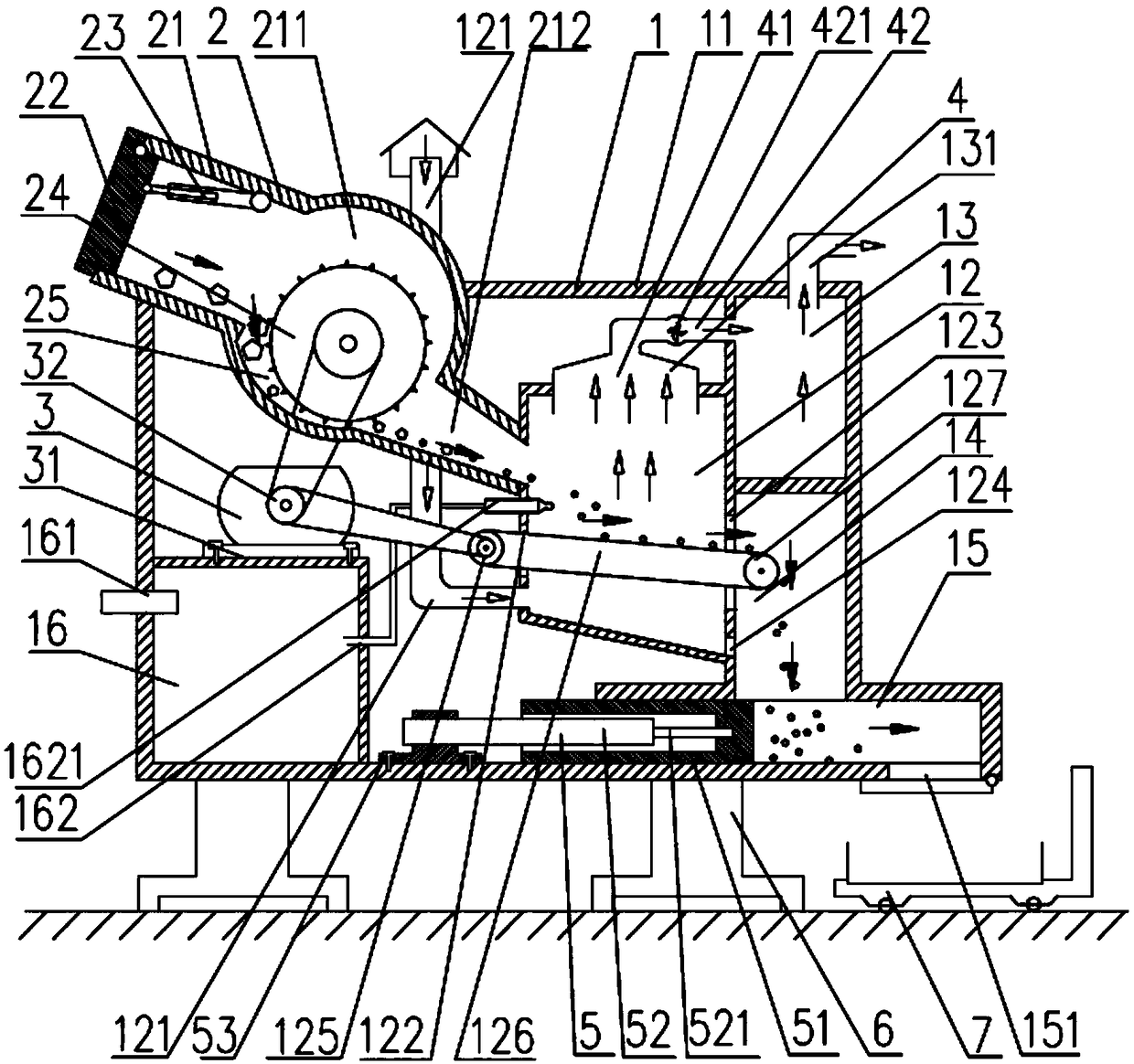
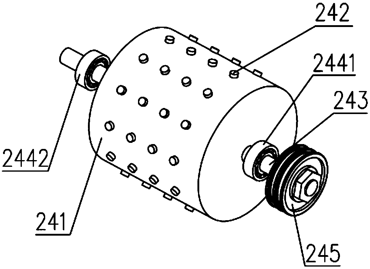
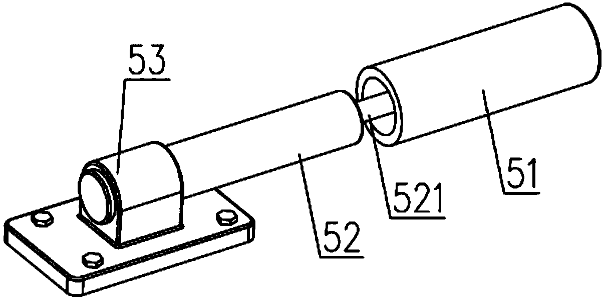
[0025] Such as Figure 1 to Figure 3As shown, the medical waste compression treatment device according to this embodiment includes a device body 1, a crushing cabin 2, a driver 3 and a compressor 5. The device body 1 includes a device casing 11, several compartments arranged in the device casing 11, The upper air intake pipeline 121 and the conveyor belt 126, the driver 3 is fixed in the device casing 11, the driver 3 i...


PUM


Abstract

The invention discloses a medical waste compression treatment device which comprises a device body, a crushing bin, a driver and a compressor. The driver is fixed in a device shell and comprises a drive motor and a drive belt wheel. A combustion chamber is arranged in the middle in the device shell. A flue gas purification chamber is arranged on the upper portion of the right side of the combustion chamber. The crushing bin is mounted on the upper portion of the left side of the device shell and inclines towards the lower right portion. A conveying belt sequentially penetrates through a feeding opening and a discharging opening, and a driving belt wheel and a driven belt wheel are arranged at the two ends of the conveying belt correspondingly. The driving belt wheel is connected with the driven belt wheel through a belt. The compressor is arranged on the left side of a compression chamber and comprises an air cylinder, a compression piston with the interior being hollow and a piston rod with the right end fixed in the compression piston. The left end of the piston rod is connected with the air cylinder. According to the medical waste compression treatment device, through the arrangement of the compression chamber, garbage fragments can be effectively extruded and compacted, later transportation is facilitated, the structure is compact, use is convenient, and energy saving and environment protection are achieved. The medical waste compression treatment device is suitable for being widely applied to medical waste treatment.

Description

technical field [0001] The invention relates to the technical field of medical waste treatment, in particular to a medical waste compression treatment device. Background technique [0002] Medical waste refers to all the waste that needs to be discarded and cannot be reused in the hospital, including biological and non-biological, as well as domestic waste; medical waste may contain a large number of pathogenic microorganisms and harmful chemicals, and may even be radioactive and damaging. Therefore, medical waste is an important risk factor for disease transmission or related public health problems. [0003] Due to the increase in the number of patients, the amount of medical waste generated during the diagnosis, treatment, and nursing activities of patients is also increasing. At present, there are big problems in the treatment of medical waste. The treatment of medical waste is not up to standard. Due to the large volume of medical waste, the transportation is cumbersome...

Claims


Application Information

Patent Timeline
Patent Type & Authority Applications(China)
IPC IPC(8): B09B3/00B30B9/30F23G5/033F23G5/44F23J15/00
CPCB09B3/0075B30B9/3057F23G5/033F23G5/44F23G5/444F23J15/00
Inventor 于大川于海洋
Owner 唐莉
Learn More