
Ladle capping and uncapping device

A technology of adding cover and ladle, which is applied in the direction of metal processing equipment, casting molten material container, casting equipment, etc., can solve the problems of poor stability of mechanism movement, failure to start, poor sealing, etc., to achieve high operation stability and occupy space Small, damage prevention effect

Pending Publication Date: 2018-11-13
MAANSHAN SHUANGYI MACHINERY MFG
View PDF0 Cites 1 Cited by
  • Summary
  • Abstract
  • Description
  • Claims
  • Application Information

AI Technical Summary

Problems solved by technology

After adding the cover, the cover is hung above the ladle mouth. Considering the phenomenon of slagging at the ladle mouth, a gap of 100mm is generally reserved between the ladle cover and the edge of the iron ladle after the cover is added. Effective thermal insulation effect;
[0005] (2) At present, the mechanism for adding and uncovering the molten iron ladle is driven by hydraulic pressure, and the movement stability of the mechanism is poor. It is difficult to ensure the synchronization of two sets of mechanisms on a chartered car
Molten iron transportation is an outdoor operation. In the severe winter in the north, the hydraulic system has many failures in the extremely low temperature environment, and even cannot be started, and the reliability of the equipment is poor.
Since the iron-clad car is equipped with a vehicle-mounted hydraulic station, it will cause a deflagration accident of the hydraulic system in case of molten iron spillage, posing a threat to the safe production of the factory

Method used


Image

  • Ladle capping and uncapping device
  • Ladle capping and uncapping device
  • Ladle capping and uncapping device

Examples


Embodiment Construction

[0026] The specific embodiment of the present invention will be described in further detail by describing the embodiments below with reference to the accompanying drawings, the purpose is to help those skilled in the art to have a more complete, accurate and in-depth understanding of the concept and technical solutions of the present invention, and contribute to its implementation.

[0027] It should be noted that in the following embodiments, the "first" and "second" do not represent an absolute distinction in structure and / or function, nor do they represent a sequence of execution, but are only for Easy to describe.

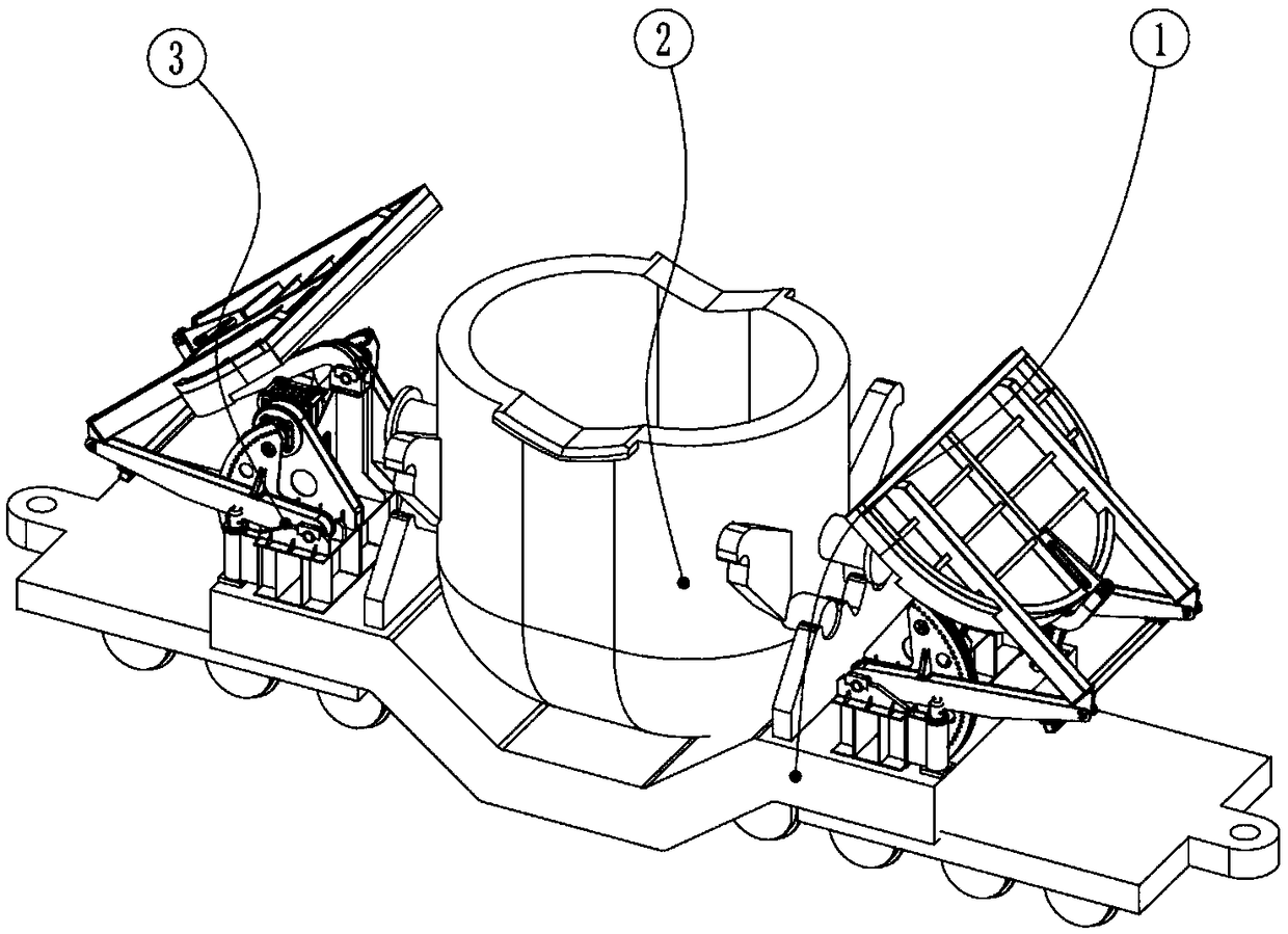
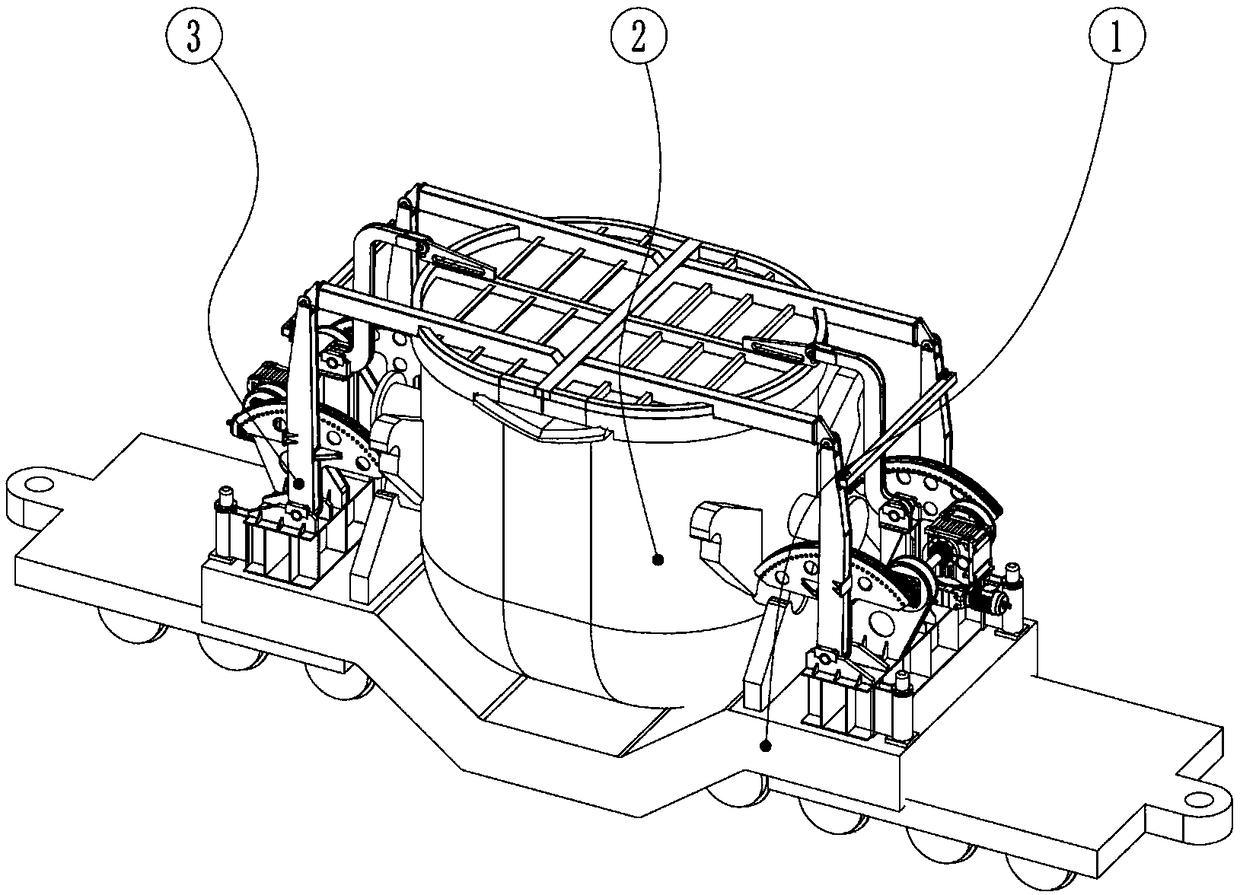
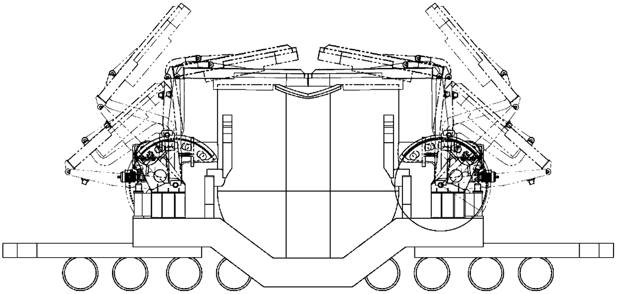
[0028] Such as Figure 1 to Figure 6 As shown, the present invention provides a ladle cover removing device, which includes a frame base 3-1, a cover, and a first active rod 3 that is rotatably arranged on the frame base 3-1 and is parallel. -2 and the second active rod 3-9, the first pin ring gear 3-15 arranged on the first active rod 3-2, the second pin rin...


PUM


Abstract

The invention discloses a ladle capping and uncapping device. The ladle capping and uncapping device comprises a rack base, a first driving rod piece, a second driving rod piece, a first pin gear ringarranged on the first driving rod piece, a second pin gear ring arranged on the second driving rod piece, a first main drive gear meshed with the first pin gear ring, a second main drive gear meshedwith the second pin gear ring, a main transmission shaft connected to the first main drive gear and the second main drive gear, and a driving mechanism which provides a driving force for the main transmission shaft to rotate, wherein the first driving rod piece and the second driving rod piece are rotationally arranged on the rack base, are parallel to each other, and are in rotational connectionwith a ladle cap. The ladle capping and uncapping device adopts a dual-rocker mechanism to ensure that the ladle cap is fastened and pressed above the edge of a ladle during capping and the ladle capcan be placed above at a certain tilt angle during uncapping, so that the ladle capping and uncapping device is prevented from being damaged by splashed molten iron during iron discharge. Meanwhile, the ladle capping and uncapping device has the advantages of small occupied area and high running stability.

Description

technical field [0001] The invention belongs to the technical field of metallurgical production equipment, in particular, the invention relates to a device for adding and uncovering a molten iron ladle. Background technique [0002] In iron and steel enterprises, open ladles are usually used to contain molten iron, and the ladles are placed on ladle cars and transported to the steelmaking operation area by railed diesel locomotives from the tap buckle. Because the blast furnace is relatively far away from the steelmaking operation area, usually up to several kilometers. The conveying route is in the open air, and the transportation and waiting time are long. Sometimes it takes a long time to wait at the steelmaking station. A large amount of heat energy of molten iron is lost, and the temperature drop of molten iron in the ladle is large, which directly leads to a low temperature of molten iron entering the furnace for steelmaking. In order to reduce the cost of steelmaking...

Claims


Application Information

Patent Timeline
IPC IPC(8): B22D41/12
CPCB22D41/12
Inventor 王飞吴金虎疏斌余斌霍双林
Owner MAANSHAN SHUANGYI MACHINERY MFG
Learn More