Valve locking press-mounting device

A technology of press-fitting device and valve lock clip, which is applied in the direction of metal processing, metal processing equipment, manufacturing tools, etc., can solve the problems of incompatibility, lock clip not falling in place, increased check work, etc., to achieve easy changeover, The effect of simple and reasonable structure and high reliability

Active Publication Date: 2018-11-13
GUANGXI YUCHAI MASCH CO LTD
View PDF6 Cites 0 Cited by
  • Summary
  • Abstract
  • Description
  • Claims
  • Application Information

AI Technical Summary

Problems solved by technology

Due to the differential influence of the lock clips during the transportation and press-fitting process of the valve lock clips, the lock clips are likely to get stuck and fall out of place during the transportation and assembly process, resulting in missed installation of the lock clips, and the reliability of the automatic press-fitting of the equipment is low. , the general pass rate is only 95-98%. It is necessary to increase the check work of manual visual inspection of whether the lock clip is missing, and manually use simple press-fitting tooling to replenish the missing lock clip again, which affects the bottleneck of production rhythm and quality. process, and when producing multi-model engine cylinder heads in a mixed line, due to the different types of lock clips and the differences in lock clip selection trays and delivery pipes, the press-fitting device cannot be compatible with various types of lock clips. The equipment needs to design a variety of material selection trays, conveying pipes, and press-fitting devices to meet the press-fitting of different types of lock clips

Method used


Image

  • Valve locking press-mounting device
  • Valve locking press-mounting device
  • Valve locking press-mounting device

Examples


Embodiment Construction

[0019] The specific embodiments of the present invention will be described in detail below in conjunction with the accompanying drawings, but it should be understood that the protection scope of the present invention is not limited by the specific embodiments.

[0020] Unless expressly stated otherwise, throughout the specification and claims, the term "comprise" or variations thereof such as "includes" or "includes" and the like will be understood to include the stated elements or constituents, and not Other elements or other components are not excluded.

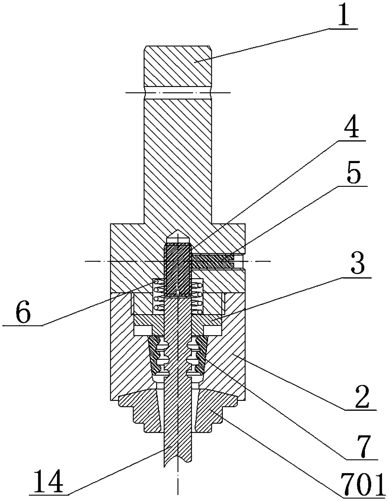
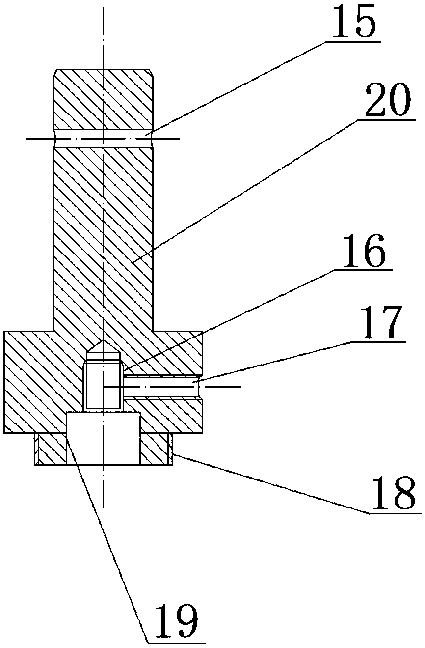
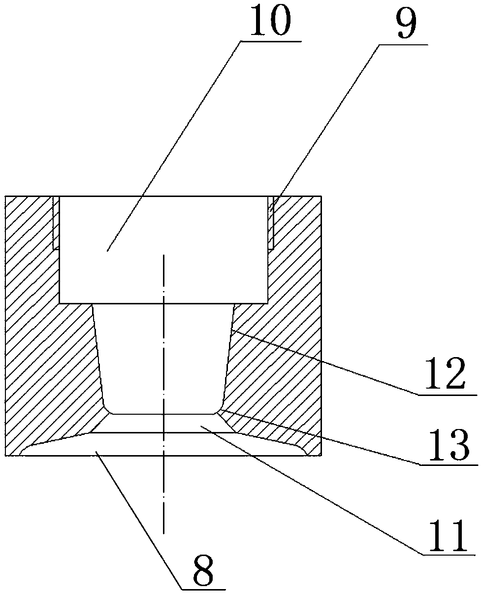
[0021] Such as Figure 1 to Figure 5 as shown, figure 1 It is a cross-sectional view of the front structure of the valve locking press-fitting device according to an embodiment of the present invention; figure 2 It is a front structural cross-sectional view of the connecting block of the valve locking press-fitting device according to an embodiment of the present invention; image 3 It is a front structural cross-sectio...


PUM


Abstract

The invention discloses a valve locking press-mounting device comprising a connecting block, a press-mounting seat and a pressing block. The lower side of the connecting block is sequentially providedwith a first through hole, a connecting rod, an adjusting screw hole and a spring hole from top to bottom; an adjusting screw rod is arranged in the adjusting screw hole, a spring is fixedly mountedin the spring hole, and a locking screw hole is formed in the right side, close to the adjusting screw hole, of the connecting rod; a locking bolt is arranged in the locking screw hole, and an outer thread is formed in the outer side, close to the spring hole, of the connecting rod; an inner hole is formed in the center of the press-mounting seat, and an inner thread is formed in the outer side, close to the inner hole, of the interior of the press-mounting seat; the inner thread is fixedly connected to the outer thread of the connecting rod; a first conical surface, a second conical surface,a round hole and a concave surface are sequentially arranged on the lower side, close to the inner hole, of the interior of the press-mounting seat from top to bottom; and a valve spring seat is arranged on the lower side of the press-mounting seat. In this way, the valve locking press-mounting device is simple and reasonable in structure and high in reliability, and the working link of manual detection and mounting supplementing is reduced.

Description

technical field [0001] The invention relates to the field of mechanical equipment manufacturing and assembly, in particular to a valve locking press-fitting device. Background technique [0002] In the engine assembly process, the cylinder head valve lock needs to be assembled in an assembly process after the valve spring and valve spring seat are assembled. At present, with the improvement of engine emission requirements, the technology of engine cylinder head intake and exhaust rods has developed into four valves, Multi-slot valve lock clip technology, a six-cylinder engine has 24 intake and exhaust valves in total, and cylinder head valve lock clip press assembly has become a bottleneck process that affects production beats and quality. At present, the press assembly process of cylinder head valve lock clips There are two kinds of manual assembly and automatic assembly. Manual assembly is to manually pre-install the valve spring, spring seat and lock clip in advance, and ...

Claims


Application Information

Patent Timeline
Patent Type & Authority Applications(China)
IPC IPC(8): B23P19/04
CPCB23P19/042
Inventor 谭伟权
Owner GUANGXI YUCHAI MASCH CO LTD
Why Eureka
Try Eureka