Fixture with positioning function

A fixture and function technology, applied in the field of machinery, can solve problems such as difficulty in grasping the distance between fixtures, inconvenient work for staff, damage to clamped items, etc., and achieve the effect of compact structure, strong practicability and saving production costs

Inactive Publication Date: 2018-11-13
柳州通亿汽车配件制造有限公司
View PDF9 Cites 4 Cited by
  • Summary
  • Abstract
  • Description
  • Claims
  • Application Information

AI Technical Summary

Problems solved by technology

[0005] Aiming at the deficiencies of the prior art, the present invention provides a clamp with a positioning function, which solves the problem that the distance between the clamps is not easy to grasp when clamping small and fragile items, and it is easy to cause damage to the clamped items , causing inconvenience to the work of the staff, causing unnecessary waste, and causing certain economic losses to the company

Method used


Image

  • Fixture with positioning function
  • Fixture with positioning function
  • Fixture with positioning function

Examples


Embodiment Construction

[0022] The following will clearly and completely describe the technical solutions in the embodiments of the present invention with reference to the accompanying drawings in the embodiments of the present invention. Obviously, the described embodiments are only some, not all, embodiments of the present invention. Based on the embodiments of the present invention, all other embodiments obtained by persons of ordinary skill in the art without making creative efforts belong to the protection scope of the present invention.

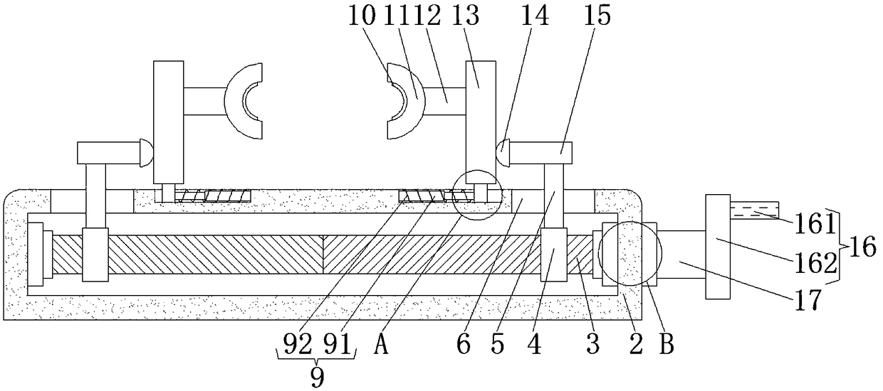
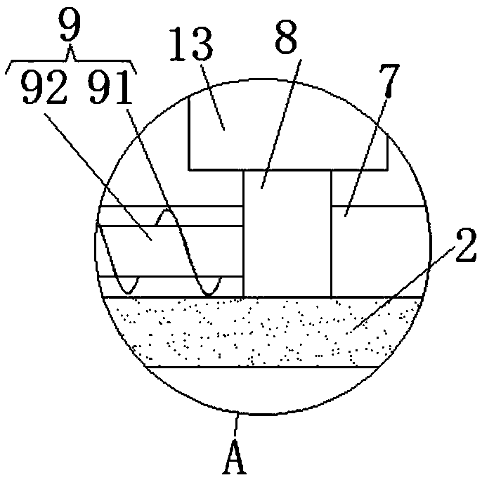
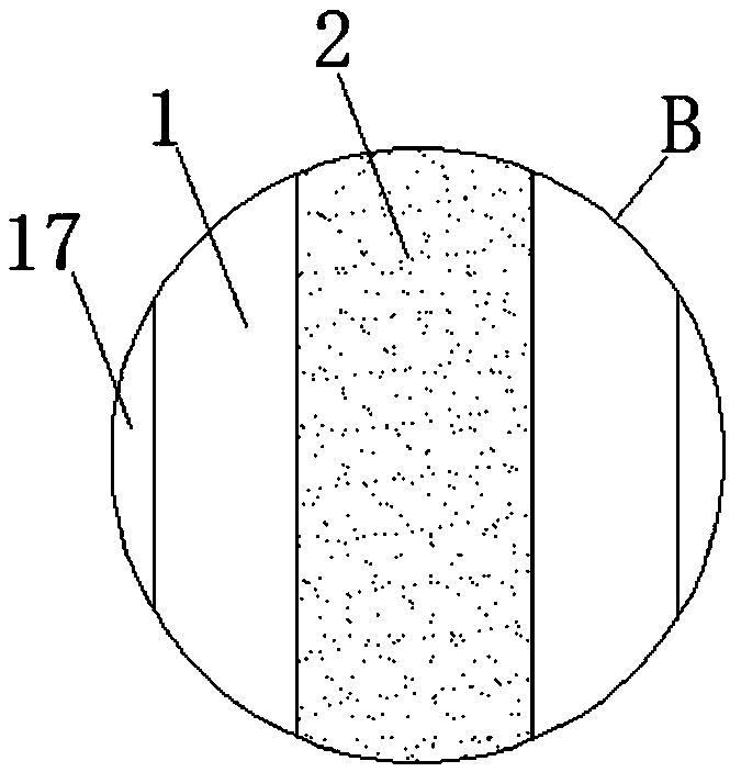
[0023] Such as Figure 1-3 As shown, the present invention provides a technical solution: a fixture with a positioning function, including a box body 2, and two chute 7 is opened on the upper surface of the box body 2, by setting the chute 7 and the slider 8, squeeze When the briquetting block 14 drives the movable plate 13 to move left and right, the movable plate 13 drives the slider 8 to move in the chute 7, which avoids the situation that the movable plate...


PUM


Abstract

The invention discloses a fixture with a positioning function, comprising a box body, wherein the upper surface of the box body is provided with two sliding grooves, sliding blocks are slidingly connected in the sliding grooves, the left side faces of the inner walls of the sliding grooves are fixedly connected with the left ends of telescopic devices, the right ends of the telescopic devices arefixedly connected with the left side faces of the sliding blocks, the upper surfaces of the sliding blocks are fixedly connected with the lower surfaces of movable plates, the left side faces of the movable plates are fixedly connected with the right ends of connecting rods, the left ends of the connecting rods are fixedly connected with the right side faces of fixing plates, the right side facesof the movable plates are fixedly connected with the left side faces of extruding blocks, and the right side faces of the extruding blocks are fixedly connected with the left ends of second movable rods. Through cooperation of handles, the fixing plates, a rotating shaft, threaded columns, threaded caps, first movable rods, the second movable rods, the extruding blocks, the movable plates, the connecting rods and a connecting plate, objects needing to be clamped can be fixed, work of a user is facilitated, fragile objects are prevented from being damaged, and the production cost is reduced.

Description

technical field [0001] The invention relates to the field of mechanical technology, in particular to a clamp with a positioning function. Background technique [0002] It is a device used to fix the processing object in the process of mechanical manufacturing so that it occupies the correct position to accept construction or inspection. In a broad sense, any process in the process, the device used to install the workpiece quickly, conveniently and safely, can be called a fixture. Such as welding fixtures, inspection fixtures, assembly fixtures, machine tool fixtures, etc. Among them, machine tool fixtures are the most common, often referred to as fixtures. [0003] The existing clamps generally control the distance between the clamps through the motor, but the disadvantage of this is that due to the mechanical control, when clamping small and fragile items, it is not easy to grasp the distance between the clamps, and it is easy to grasp the distance between the clamps. Th...

Claims


Application Information

Patent Timeline
Patent Type & Authority Applications(China)
IPC IPC(8): B23Q3/06
Inventor 黄海光罗丙球
Owner 柳州通亿汽车配件制造有限公司
Why Eureka
Try Eureka