Eureka AIR delivers breakthrough ideas for toughest innovation challenges, trusted by R&D personnel around the world.

Ink box for copying machine

A technology for copiers and ink cartridges, applied in printing, mixers, mixers with rotating agitation devices, etc., can solve problems such as inability to make normal copies, achieve the effects of shortening the waiting time, improving the mixing effect, and improving the overall sense of use

Active Publication Date: 2018-11-13
贵州省仁怀市西科电脑科技有限公司
View PDF12 Cites 6 Cited by
  • Summary
  • Abstract
  • Description
  • Claims
  • Application Information

AI Technical Summary

Problems solved by technology

[0004] The purpose of the present invention is to provide an ink cartridge for copiers to solve the problem that the ink cartridges in the prior art cannot be copied normally due to ink being frozen

Method used


Image

  • Ink box for copying machine

Examples


Embodiment Construction

[0020] The following is further described in detail through specific implementation methods:

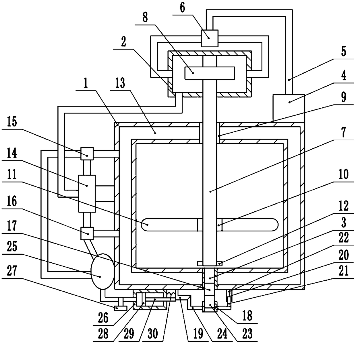
[0021] The reference signs in the drawings of the description include: ink cartridge body 1, air guide box 2, ink outlet 3, air supply box 4, conduit 5, first three-way valve 6, rotating shaft 7, turbine 8, sealing ring 9, sliding sleeve 10 , stirring plate 11, limit block 12, cavity 13, vortex tube 14, second three-way valve 15, third three-way valve 16, quick female connector 17, ink outlet channel 18, sealing plate 19, outer casing rod 20, Inner sleeve rod 21, second spring 22, quick male connector 23, wedge bar 24, air bag 25, cylinder block 26, first regulating valve 27, piston 28, piston rod 29, first spring 30.

[0022] The embodiment is basically as attached figure 1 Shown:

[0023] An ink cartridge for copiers, comprising an ink cartridge body 1 and an air guide box 2, an ink outlet 3 is opened on the bottom of the ink cartridge body 1, two air inlets and an air outlet are...


PUM


Abstract

The invention relates to the technical field of copying machine equipment and discloses an ink box for a copying machine. The ink box comprises an ink box body and an air guiding box. The ink box bodyis provided with an ink outlet. The air guiding box is provided with air inlets and an air outlet. The ink box body is provided with an air supply box. A guide pipe communicates with the air supply box and is provided with a first three-way valve. The first three-way valve communicates with the air inlets. A rotating shaft is connected into the air guiding box in a rotary manner. A turbine is connected to the rotating shaft in a sleeving manner. One end of the rotating shaft penetrates the air guiding box and extends into the ink box body. A sliding sleeve is connected to the rotating shaft in a sleeving and threaded manner. A stirring plate is fixedly connected to the sliding sleeve. A cavity is formed in the inner wall of the ink box body. A vortex tube is fixedly connected to the ink box body, wherein the vortex tube communicates with the air outlet. The hot air end and the cold air end of the vortex tube each communicate with the cavity. A second three-way valve is connected between the hot air end of the vortex tube and the cavity. A third three-way valve is connected between the cold air end of the vortex tube and the cavity. By means of the ink box, the problem that in theprior art, due to the fact that ink in an ink box is frozen, normal coping cannot be conducted is solved.

Description

technical field [0001] The invention relates to the technical field of copier equipment, in particular to an ink box for a copier. Background technique [0002] As an important part of the copier, the ink cartridge usually has a cartridge body, an ink chamber, a chip, a pressure controller and other components. The inkjet copier supplies ink from the ink cartridge, and transports the ink to the ink nozzle through the ink delivery tube, and the nozzle ejects the ink onto the paper under the drive of the control command to complete the printing of characters. [0003] The ink cartridges in the prior art have the following technical problems: 1. In the case of low temperature, because the ink is easily frozen, it cannot be supplied normally, so that the copier cannot copy normally. Remove it from the copier, heat it (such as using a hair dryer to blow hot air) to melt the ink, and then install the ink cartridge into the copier for use. The problem with this method is that the ...

Claims


Application Information

Patent Timeline
Patent Type & Authority Applications(China)
IPC IPC(8): B41J2/175B01F7/18
CPCB41J2/17513B41J2/17556B41J2/17596B01F27/90B01F2101/35
Inventor 余洪科余忠保刘秋
Owner 贵州省仁怀市西科电脑科技有限公司
Why Eureka
Eureka Blog
Learn More