
Macro-micro combined adjustment device

A technology of adjustment device and movable surface, applied in wing adjustment, transportation and packaging, body and other directions, can solve the problems of unable to achieve large stroke adjustment, unable to meet precise adjustment, limited to millimeter level, etc., to meet the requirements of miniaturized design , light weight, meet the effect of large stroke adjustment and fine adjustment

Inactive Publication Date: 2018-11-13
GUANGDONG UNIV OF TECH
View PDF11 Cites 1 Cited by
  • Summary
  • Abstract
  • Description
  • Claims
  • Application Information

AI Technical Summary

Problems solved by technology

[0002] For some displacement settings, such as automobiles, airplanes, etc., the adjustment devices are all driven by one-dimensional macro, that is, mechanical transmission devices, such as precision screw power transmission, linear motors, voice coil motors, etc. The structure of this device is bulky, The accuracy is low, and its accuracy is limited to the millimeter level, which cannot meet the needs of precise adjustment, especially for some small aircraft with many changes in flight attitude; and the micro-drive device represented by piezoelectric ceramics, its positioning accuracy can reach nanometer level , but its stroke can only reach tens of microns, and the adjustment of large stroke cannot be realized, so it is necessary to use a macro-micro adjustment device to solve the above problems
[0003] The existing macro-micro-combined composite mechanism is mostly used in the field of machine tools and precision machining. In terms of precision control of the adjustment device, the macro-micro-combined adjustment mechanism is rarely used.

Method used


Image

  • Macro-micro combined adjustment device
  • Macro-micro combined adjustment device
  • Macro-micro combined adjustment device

Examples


Embodiment Construction

[0028] In order to make the object, technical solution and advantages of the present invention clearer, the present invention will be further described in detail below in conjunction with the accompanying drawings. It is only stated here that the words for directions such as up, down, left, right, front, back, inside, and outside that appear or will appear in the text of the present invention are only based on the accompanying drawings of the present invention, and are not specific to the present invention. limited.

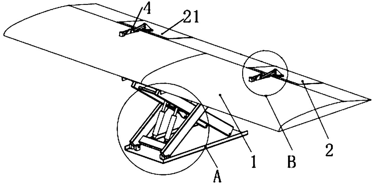
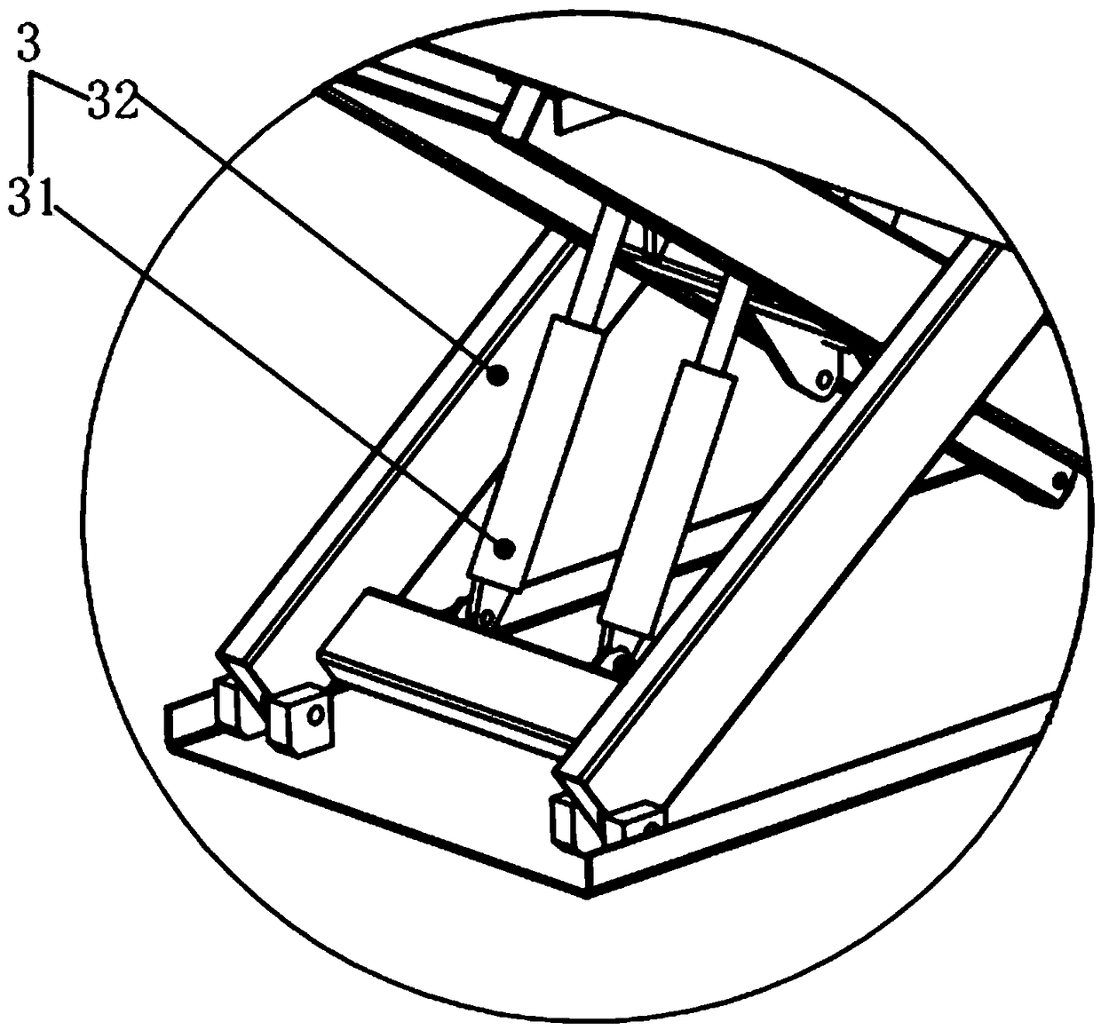
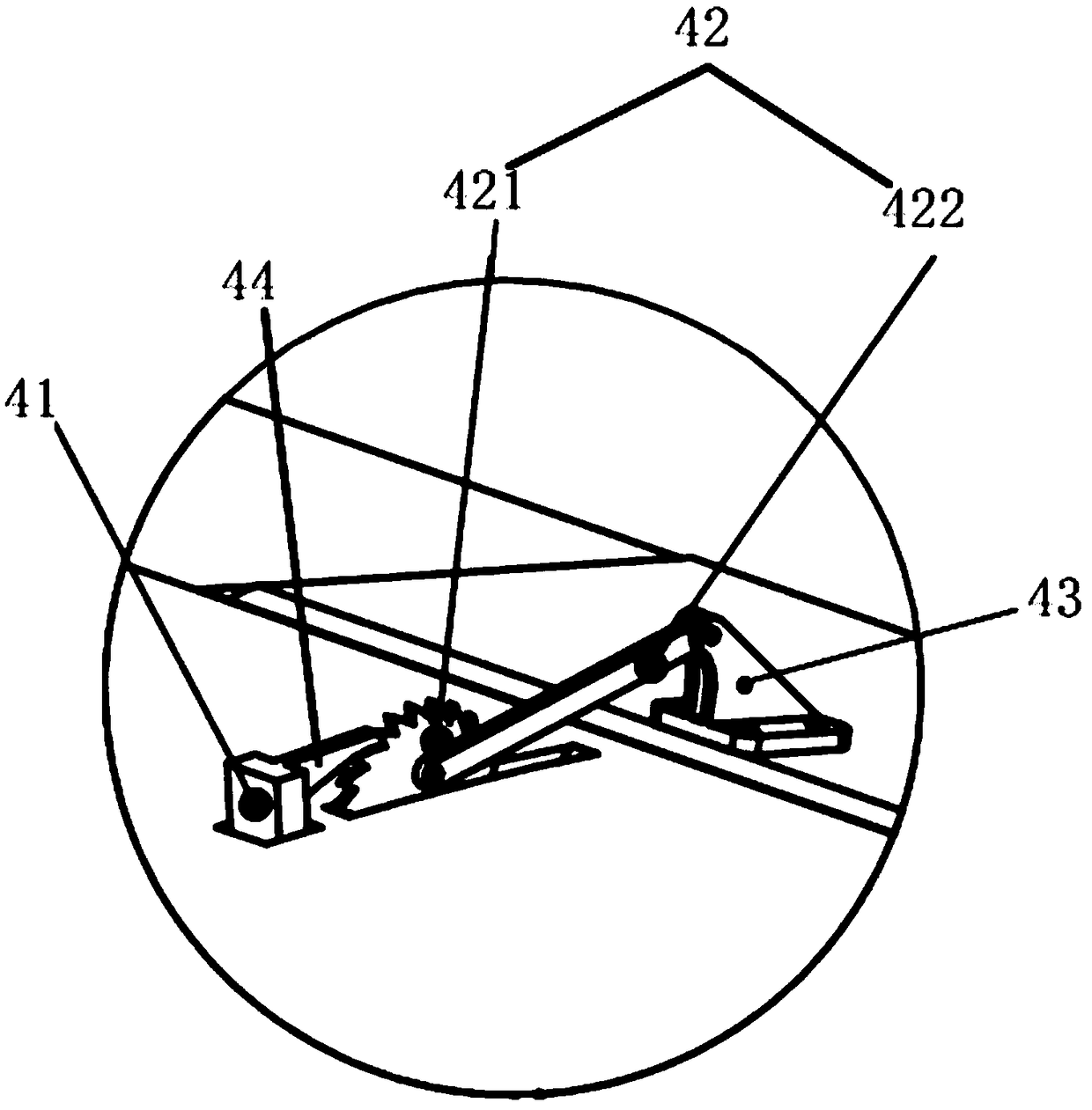
[0029] Such as Figure 1-3 As shown, the embodiment of the present invention provides a macro-micro-integrated adjustment device, including a first movable surface 1, a second movable surface 2 connected to the first movable surface 1, and a second movable surface 2 connected to the first movable surface 1. The connected hydraulic drive mechanism 3 and the piezoelectric drive mechanism 4 connected with the second movable surface 2;

[0030] The piezoelectric dr...


PUM


Abstract

The invention discloses a macro-micro combined adjustment device. The macro-micro combined adjustment device comprises a first movable surface, a second movable surface connected to the first movablesurface, a hydraulic driving mechanism connected to the first movable surface and a piezoelectric driving mechanism connected to the second movable surface. The piezoelectric driving mechanism includes a ceramic driver, a connecting mechanism connected to the ceramic driver and a connecting block connected to the connecting mechanism. The connecting mechanism is connected to the ceramic driver andthe connecting block separately. According to the macro-micro combined adjustment device, coarse adjustment of the first movable surface is realized by the hydraulic driving mechanism, and fine adjustment of the second movable surface is realized by the piezoelectric driving mechanism; and adjustment can be performed according to the actual needs, the hydraulic driving mechanism and / or the piezoelectric driving mechanism is selected to achieve the attitude adjustment, the adjustment accuracy is high, and the market demand for high difficult adjustment is met.

Description

technical field [0001] The invention relates to the technical field of displacement driving equipment, in particular to an adjustment device combining macro and micro. Background technique [0002] For some displacement settings, such as automobiles, airplanes, etc., the adjustment devices are all driven by one-dimensional macro, that is, mechanical transmission devices, such as precision screw power transmission, linear motors, voice coil motors, etc. The structure of this device is bulky, The accuracy is low, and its accuracy is limited to the millimeter level, which cannot meet the needs of precise adjustment, especially for some small aircraft with many changes in flight attitude; and the micro-drive device represented by piezoelectric ceramics, its positioning accuracy can reach nanometer level , but its stroke can only reach tens of microns, and the adjustment of large stroke cannot be realized. Therefore, it is necessary to use a macro-micro adjustment device to solve...

Claims


Application Information

Patent Timeline
Patent Type & Authority Applications(China)
IPC IPC(8): B62D35/00B64C3/38
CPCB62D35/007B64C3/38
Inventor 陈桪何超陈章俊吴国庆
Owner GUANGDONG UNIV OF TECH
Learn More