Fiber rod cutting device of carding machine coiler

A technology of cutting device and sliver coiler, which is applied in fiber processing, deburring device, textile and paper making, etc. It can solve the problems of reduced sliver speed and impact on production efficiency, and achieves reasonable position setting, simple structure and good reliability. Effect

Pending Publication Date: 2018-11-13
QINGDAO HONGDA TEXTILE MACHINERY
View PDF7 Cites 0 Cited by
  • Summary
  • Abstract
  • Description
  • Claims
  • Application Information

AI Technical Summary

Problems solved by technology

Because the speed of the strips is reduced when cutting the strips, which affects the production efficiency

Method used


Image

  • Fiber rod cutting device of carding machine coiler
  • Fiber rod cutting device of carding machine coiler

Examples


Embodiment Construction

[0020] The present invention is described in further detail below in conjunction with accompanying drawing:

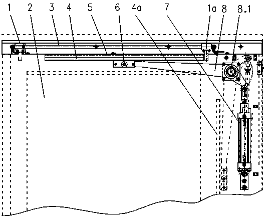
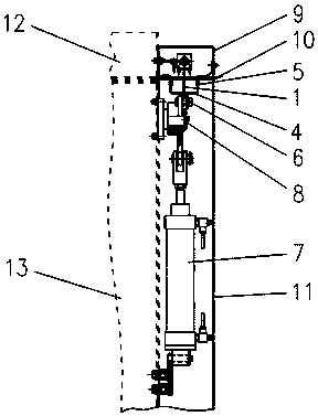
[0021] see figure 1 , figure 2 , an embodiment of a fiber strip cutting device of a carding machine coiler of the present invention, comprising a fiber strip cutting device, a coiler large column 13, a coil top box 12, a can 2 comprising a working cylinder and a full cylinder, The sliver cutting device is set between the working cylinder and the full cylinder close to the coiler, figure 2 The sliver cutting device is shown on the left in the mandrel position and on the right in the full drum position. The fiber strip cutting device includes a cutter 1, a strip cutting cylinder 3, a u-shaped support plate 4, a u-shaped support plate swing center shaft 6, a swing arm cylinder 7, a swing arm 8, a swing arm rotation center shaft 8.1 and a strip cutting support base plate 10. The swing arm cylinder 7 is vertically fixed on one side of the large column 13 of the coiler....


PUM


Abstract

The invention provides a fiber rod cutting device of a carding machine coiler. The fiber rod cutting device is characterized by being arranged on the position close to the portion between a coiler working barrel and a full barrel, the fiber rod cutting device comprises a cutter, a slicing cylinder, a u type support plate, a u type support plate swing center shaft, a swing arm cylinder, a swing arm, a swing arm rotating center shaft and a slicing support base plate, the swing arm cylinder is vertically fixed to one side of a coiler larger post, the middle of the swing arm is hinged and fixed through the swing arm rotating center shaft, one end of the swing arm is hinged to the upper end of a vertical telescopic cylinder of the swing arm cylinder, and the other end of the swing arm is hingedto the middle of the u type support plate through the u type support plate swing center shaft. The slicing support base plate is arranged on the upper portion of the u type support plate, the slicingcylinder is arranged on the upper portion of the slicing support base plate, and a horizontally moving sliding block of the slicing cylinder is connected with the cutter. The device can work on the condition that a carding machine discharges at a high speed, the success rate of fiber cut cutting is ensured, the production efficiency is improved, the structure is simple, and convenience is broughtto manufacturing, assembling and debugging.

Description

technical field [0001] The invention belongs to the technical field of textile machinery manufacturing, and relates to a fiber strip cutting device for a coiler of a carding machine. Background technique [0002] Existing automatic can changing coiler has guide rack, end-breaking device, small pressure roller roller, coiling device and automatic can changing device. The sliver enters the bell mouth of the end-breaking device through the sliver guide, and is transferred to the sliver coiling device through the small roller roller. After setting the value, the automatic can changing device will move out the full can and move in the empty can, and at the same time, the end-breaking device will break the sliver, and the sliver in the full can will be used in the subsequent process. [0003] Chinese Invention Patent (Application No. 201610414526.3) discloses a "end-breaking device for coiler", a bell mouth, small tongue, spring, pneumatic flip-type broken bar in front of the sma...

Claims


Application Information

Patent Timeline
Patent Type & Authority Applications(China)
IPC IPC(8): D01G15/12
CPCD01G15/12
Inventor 邵明东陈朝龙倪敬达
Owner QINGDAO HONGDA TEXTILE MACHINERY
Why Eureka
Try Eureka