
Cutting device of non-woven fabric

A cutting device and non-woven fabric technology, applied in the cutting of textile materials, textiles and papermaking, etc., can solve the problems of low precision, inconvenient operation, slow cutting speed, etc., achieve high degree of automation, reduce work intensity, and increase cutting speed Effect

Active Publication Date: 2018-11-13
HUZHOU PINCHUANG INCUBATOR
View PDF5 Cites 1 Cited by
  • Summary
  • Abstract
  • Description
  • Claims
  • Application Information

AI Technical Summary

Problems solved by technology

[0002] Non-woven fabric processing equipment has a wide range of needs in textile enterprises or plastic manufacturing enterprises. Usually, non-woven fabrics need to be cut. Traditional cutting equipment cannot adapt to today's production needs due to its low precision and slow cutting speed. Now the market Most of the cutting equipment in the world is large in size and inconvenient to operate. The entire non-woven fabric to be cut is placed on the cutting panel, and the cutting panel drives the fabric to move, so that the guillotine can cut the fabric. The efficiency of this kind of cutting fabric is low. Moreover, the movement of the non-woven fabric on the cutting panel needs to be manually pulled, and after each cutting, the fabric needs to be placed on the cutting panel again, which is time-consuming and laborious, and increases the work intensity of the operator

Method used

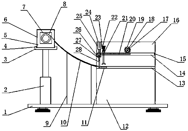
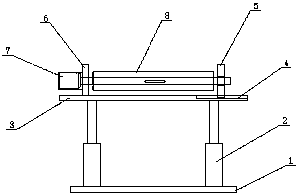
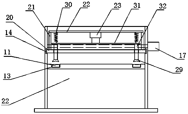

Image

  • Cutting device of non-woven fabric
  • Cutting device of non-woven fabric
  • Cutting device of non-woven fabric

Examples


Embodiment Construction

[0018] The following will clearly and completely describe the technical solutions in the embodiments of the present invention with reference to the accompanying drawings in the embodiments of the present invention. Obviously, the described embodiments are only some, not all, embodiments of the present invention. Based on the embodiments of the present invention, all other embodiments obtained by persons of ordinary skill in the art without making creative efforts belong to the protection scope of the present invention.

[0019] see Figure 1~4 , in an embodiment of the present invention, a non-woven fabric cutting device includes a base 1, a hydraulic cylinder 2, a horizontal plate 3, a wedge-shaped groove 4, a moving block 5, a fixed block 6, a first motor 7, and a cloth roller 8 , bracket 9, arc-shaped support frame 10, slider 11, support seat 12, chute one 13, chute two 14, limit block 15, support plate 16, second motor 17, straight rack 18, gear 19, Partition plate 20, co...


PUM


Abstract

The invention discloses a cutting device of a non-woven fabric. A wedge-shaped groove is formed in one end of a first transverse plate, a wedge-shaped block is arranged at the bottom of a movable block, the movable block is slidably arranged in the wedge-shaped groove of the first transverse plate through the wedge-shaped block at the bottom, and a fixed block is fixedly arranged at the other endof the first transverse plate; a first motor is arranged on one side of the fixed block through a motor mounting base, the output end of the first motor is provided with a rotating shaft through a coupler, a cloth roller is fixedly arranged on the rotating shaft through a key, and supporting plates are vertically arranged on the two sides of a supporting base respectively; second sliding grooves are formed in the horizontal directions of the supporting plates on the two sides of the supporting base, and a partition plate is slidably connected with the interiors of the second sliding grooves ofthe supporting plates; sliding rods are arranged at the two ends of the other side of a third transverse plate respectively, and through holes allowing the sliding rods to penetrate through are formed in the partition plate; a sucker is fixedly arranged at the other end of each sliding rod.

Description

technical field [0001] The invention relates to the technical field of cutting equipment, in particular to a cutting device for non-woven fabrics. Background technique [0002] Non-woven fabric processing equipment has a wide range of needs in textile enterprises or plastic manufacturing enterprises. Usually, non-woven fabrics need to be cut. Traditional cutting equipment cannot adapt to today's production needs due to its low precision and slow cutting speed. Now the market Most of the cutting equipment in the world is large in size and inconvenient to operate. The entire non-woven fabric to be cut is placed on the cutting panel, and the cutting panel drives the fabric to move, so that the guillotine can cut the fabric. The efficiency of this kind of cutting fabric is low. Moreover, the movement of the non-woven fabric on the cutting panel requires manual pulling, and after each cutting, the fabric needs to be placed on the cutting panel again, which is time-consuming and l...

Claims


Application Information

Patent Timeline
Patent Type & Authority Applications(China)
IPC IPC(8): D06H7/02
CPCD06H7/02
Inventor 杨海峰
Owner HUZHOU PINCHUANG INCUBATOR
Learn More