Al technical title is built by PatSnap Al team. It summarizes the technical point description of the patent document.
A cleaning equipment and multi-functional technology, which can be used in road cleaning, cleaning methods, construction, etc., and can solve the problems of multiple manpower for road cleaning, being suspended by vehicles, and being hung by the wind.
Inactive Publication Date: 2018-11-13
侯明明
View PDF4 Cites 6 Cited by
Summary
Abstract
Description
Claims
Application Information
AI Technical Summary
This helps you quickly interpret patents by identifying the three key elements:
Problems solved by technology
Method used
Benefits of technology
Problems solved by technology
The traditional sprinkler just sprinkles water on the road surface, which has achieved the purpose of reducing dust, but when the water evaporates, the dust is carried by the car and the wind.
However, cleaning the road requires a lot of manpower and time
Method used
Image
Click on the blue label to locate the original text in one second.
Reading with bidirectional positioning of images and text.
Examples
specific Embodiment approach 1
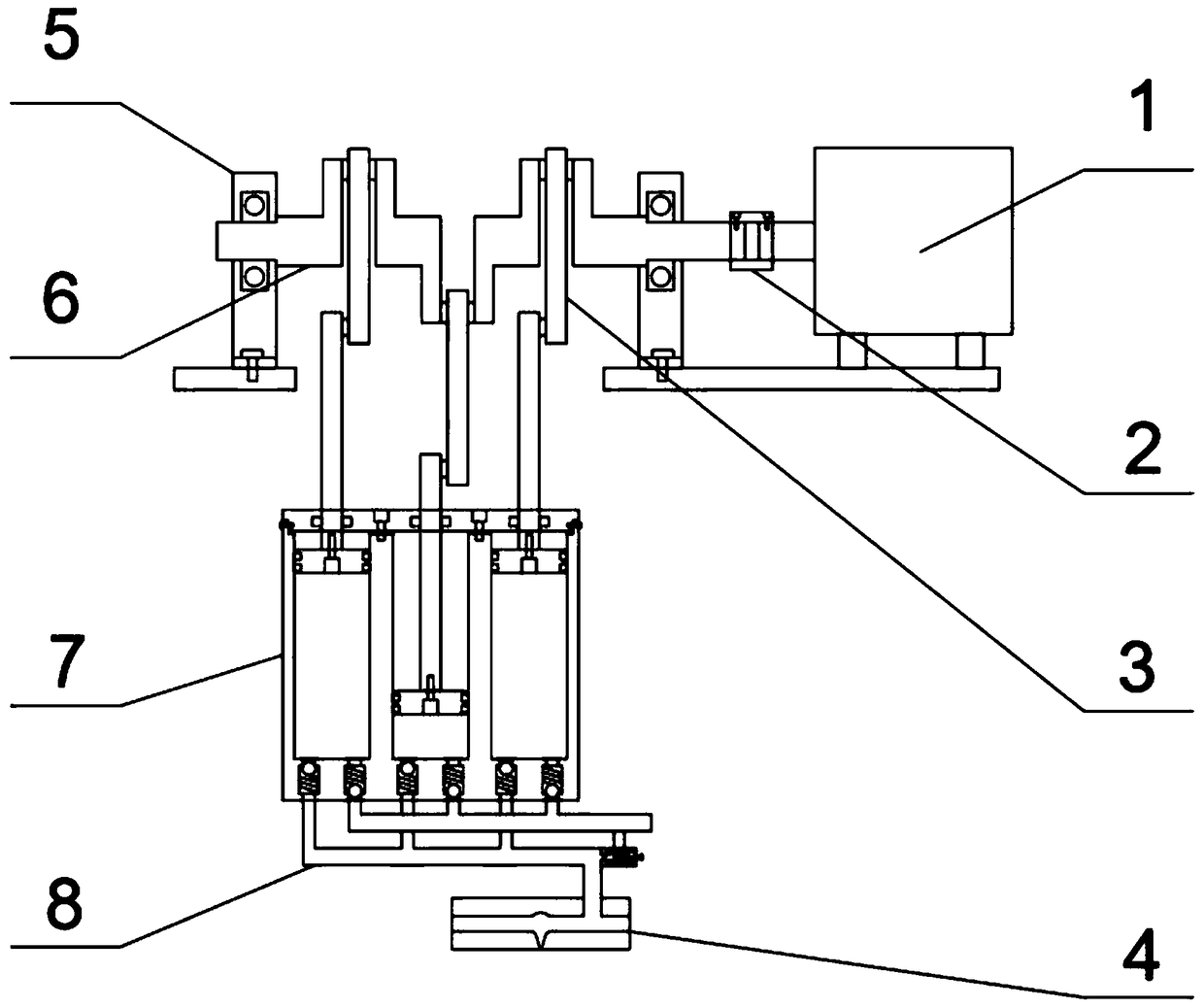
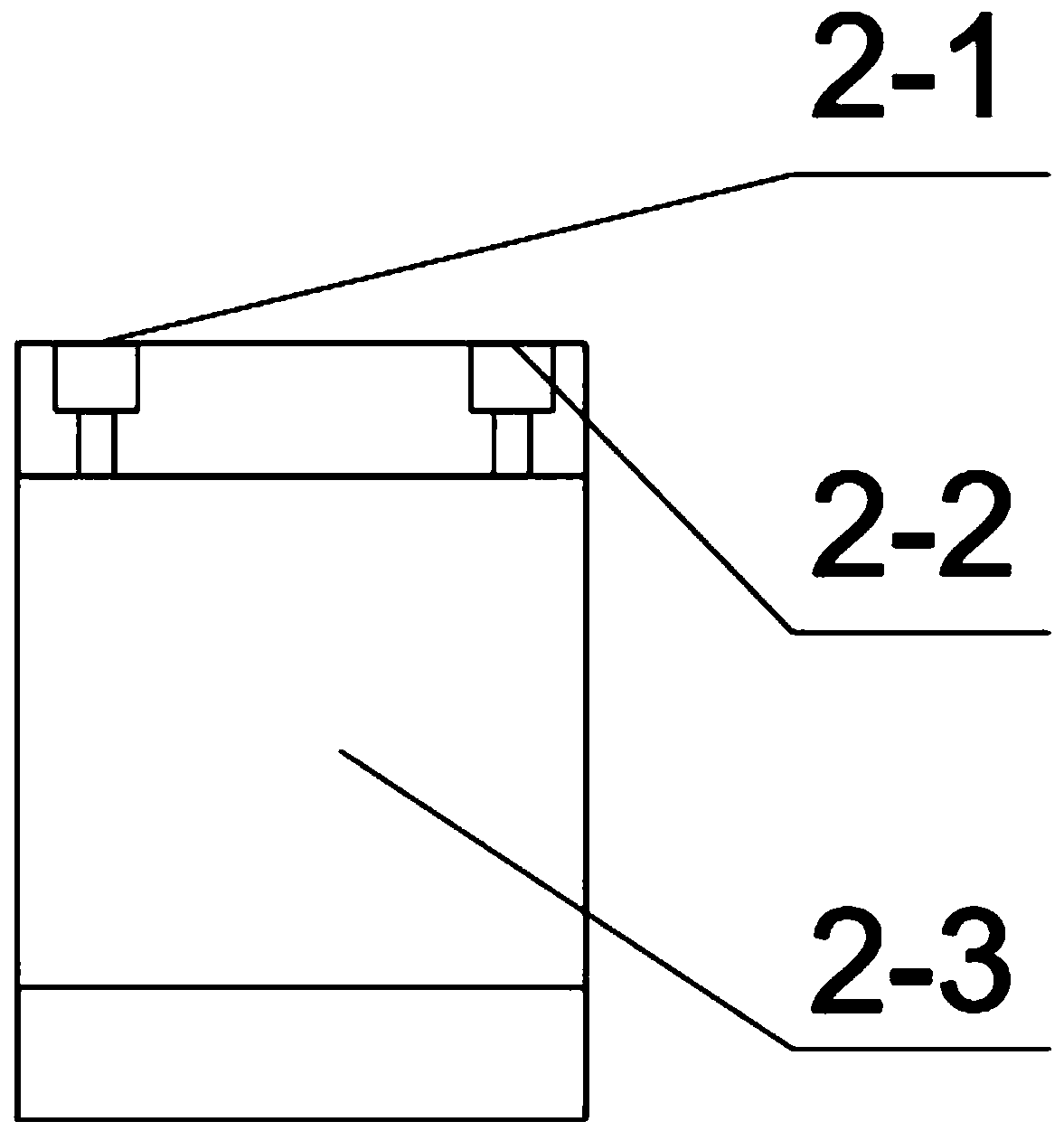
[0040] Combine below figure 1 , 2 , 3, 4, 5, 6, 7, 8, 9, 10, 11, 12, 13, 14 illustrate this embodiment, the present invention relates to a cleaning equipment, more specifically a multifunctional high-pressure road cleaning equipment , including motor 1, coupling 2, connecting rod 3, nozzle 4, bearing frame 5, crankshaft 6, pump 7, water pipe 8, not only the pressure of water spray can be adjusted through the safety pressure regulating valve to achieve a suitable working pressure , and the high-pressure water can take away the road dust and flow away through the sewer, so as to achieve the purpose of cleaning.
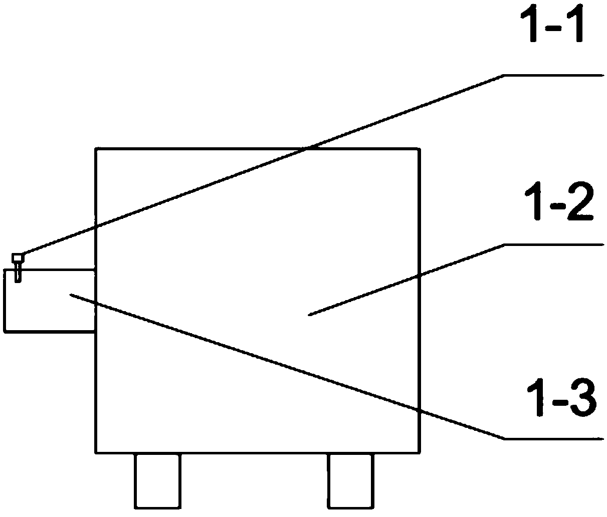
[0041] Motor 1 is made up of fastening screw 1-1, motor 1-2, rotating shaft 1-3; Fastening screw 1-1 is positioned at the left end of rotating shaft 1-3, and fastening screw 1-1 is screwed with rotating shaft 1-3; Motor 1-2 is fixed on the upper part of the bracket; the left side of the rotating shaft 1-3 is connected to the coupling 2, and the right side of the rotat...
specific Embodiment approach 2
[0055] Combine below figure 1 , 2 , 3, 4, 5, 6, 7, 8, 9, 10, 11, 12, 13, and 14 illustrate this embodiment, and this embodiment will further describe Embodiment 1. The fastening screw 1-1 and the rotating shaft 1 -3 Compressed by thread.
specific Embodiment approach 3
[0056] Combine below figure 1 , 2 . Two, the opening directions of the two piston rings 7-1-4 are opposite.
PUM
Abstract
The invention relates to cleaning equipment, in particular to multifunctional high-pressure road cleaning equipment, which can not only adjust the pressure of water spray through a safety pressure adjusting valve to achieve proper using pressure, but also can take away road dust through high-pressure water and flowing the dust away through a sewer, thereby achieving the purpose of cleaning. A motor is fixed on the upper part of a bracket, and the left side of the motor is fixed to a shaft coupling; the shaft coupling is a hollow cylinder, the left side of the shaft coupling is fixed to a crankshaft, and the right side of the shaft coupling is fixed to a motor shaft; three connecting rods are arranged, the upper parts of the connecting rods are connected with the crankshaft, and the lower parts of the connecting rods are connected with a piston; spray pipes are positioned at the lower parts of water outlet pipes, are hollow cylinders respectively and are provided with nozzles; two bearing frames are arranged and fixed on the bracket, and the middle parts of the bearing frames penetrate through the crankshaft; the crankshaft is provided with three bends, the crankshaft is connected with the connecting rods, and the crankshaft and the shaft coupling are fixed together; a pump is connected with the crankshaft through the connecting rods, and the lower part of the pump is connectedwith water pipes.
Description
technical field [0001] The invention relates to a cleaning device, in particular to a multifunctional high-pressure road cleaning device. Background technique [0002] In the city, cars come and go, and there is a lot of dust. Road cleaning requires a lot of manpower and time. The traditional sprinkler just sprinkles water on the road surface to achieve the purpose of reducing dust, but when the water evaporates, the dust is carried by the car and hung by the wind. However, cleaning the road requires a lot of manpower and time. In order to clean and quickly clean the road dust. So this multifunctional high pressure road cleaning equipment was designed. Contents of the invention [0003] The invention provides a multi-functional high-pressure road cleaning equipment, which has the beneficial effect that not only the pressure of water spray can be adjusted through a safety pressure regulating valve to achieve a suitable operating pressure, but also the high-pressure wate...
Claims
Application Information
Patent Timeline
Application Date:The date an application was filed.
Publication Date:The date a patent or application was officially published.
First Publication Date:The earliest publication date of a patent with the same application number.
Issue Date:Publication date of the patent grant document.
PCT Entry Date:The Entry date of PCT National Phase.
Estimated Expiry Date:The statutory expiry date of a patent right according to the Patent Law, and it is the longest term of protection that the patent right can achieve without the termination of the patent right due to other reasons(Term extension factor has been taken into account ).
Invalid Date:Actual expiry date is based on effective date or publication date of legal transaction data of invalid patent.