Annulus flow control nipple of oil and gas well and application method thereof
A technology for oil and gas wells and annulus, which is applied in the development of fluids, drilling equipment, earth-moving drilling, etc., can solve the problems of lack of tools and methods to control the state of annular fluid, and achieve the effect of reducing damage
- Summary
- Abstract
- Description
- Claims
- Application Information
AI Technical Summary
Problems solved by technology
Method used
Image
Examples
Embodiment 1
[0048] figure 1 It is a schematic diagram of the structure of the oil and gas well annulus flow control nipple (connection) of the present invention. The oil and gas well annular flow control nipple (joint) of the present invention includes: nipple pipe body 1-1, brush wire (hair) 1-2, and brush wire attachment body 1-3.
[0049] The pup pipe body 1-1 can be an oil pipe pup joint, or other pipe pup joints, which are common oilfield pipes.
[0050] The brush wires (hairs) 1-2 are general-purpose materials, such as metal wires and abrasive wires with high elasticity and hardness, and the brush wires that can be selected according to needs include metal wires, nylon wires, plastic wires, and abrasive wires. , sisal, mountain palm, bristle.
[0051] The brush filament attachment 1-3 is convenient to fix the carrier of the bristles, the same as others in the brush industry, and belongs to the known content in the field of brush making, so it will not be described here.
[0052] ...
Embodiment 2
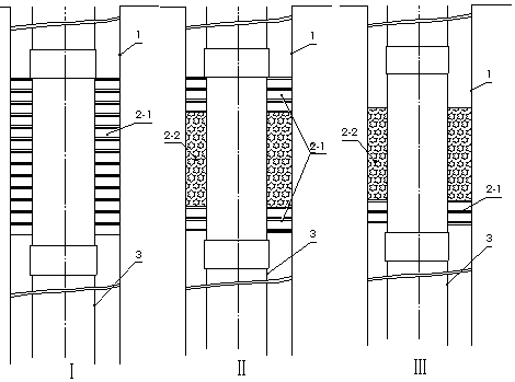
[0054] figure 2 It is a schematic diagram of the basic flow control unit when the annular space flow control nipple (connection) of the oil and gas well of the present invention is applied. There are several main basic types. The basic type I includes: the inner wall of the well 1, the annular space flow control nipple in series, and The bristles filling the annulus form a semi-permeable packing ring (bristle ring 2-1 for short); the basic type II includes: the inner wall of the well 1, the outer wall of the pipe string, the bristle ring 2-1 and the semi-permeable packing ring 2-2 of solid particles The basic type III includes: the well wall 1, the outer wall of the pipe string, the bristle ring 2-1, and the solid particles on one side of the bristle ring 2-1 form a semi-permeable packing ring 2-2.
[0055] A plurality of annular space flow control pipe string units may be connected in series to form an annular space flow control pipe string unit group 2 .
[0056] The semi-...
Embodiment 3
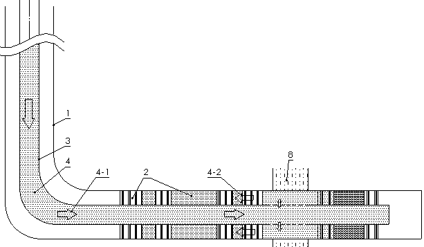
[0059] When carrying out high-energy gas fracturing construction, for the sake of construction safety, the blocking pressure of well fluid is usually relied on to ensure the efficiency of high-energy gas fracturing. In fact, the pressure of the liquid column is far from enough to suppress the energy of the high-energy gas overflow, and the effect is not ideal. However, the application of the existing isolation technology is complex and will cause safety accidents. Such as image 3 As shown, the present invention blocks and reduces the flow of gas energy from the annulus by arranging at least one basic flow control unit II to form a semi-permeable sealing layer of the flow control unit group 2 above the high-energy gas fracturing device 5. overflow. When the high-energy gas and driven well fluid pass through the annular flow control pipe string unit (group) 2, especially when the semi-permeable isolation ring section 2-2 is formed by the solid particle filling, the gaps betwee...
PUM
 Abstract
Description
Claims
Application Information
 - R&D
- Intellectual Property
- Life Sciences
- Materials
- Tech Scout
- Unparalleled Data Quality
- Higher Quality Content
- 60% Fewer Hallucinations
Browse by: Latest US Patents, China's latest patents, Technical Efficacy Thesaurus, Application Domain, Technology Topic, Popular Technical Reports.
© 2025 PatSnap. All rights reserved.Legal|Privacy policy|Modern Slavery Act Transparency Statement|Sitemap|About US| Contact US: help@patsnap.com


