Horizontal well cable protection device and application method

A cable protection and horizontal well technology, which is used in the installation of cables, the arrangement of cables between relative moving parts, electrical components, etc. problems, to achieve rapid positioning and installation, prevent contact friction, and ensure the effect of stable installation

Pending Publication Date: 2018-11-13
HEILONGJIANG LANDE ULTRASONIC TECH CO LTD
View PDF1 Cites 1 Cited by
  • Summary
  • Abstract
  • Description
  • Claims
  • Application Information

AI Technical Summary

Problems solved by technology

The device can prevent the scratching and wear of the logging cable on the tubing collar and the tubing mouth, and prolong the life of the logging cable; however, the device cannot realize quick positioning and installation, cannot ensure that the device is stable at the wellhead, and cannot prevent the device from falling into the well, and Cable cannot be cleaned

Method used


Image

  • Horizontal well cable protection device and application method
  • Horizontal well cable protection device and application method
  • Horizontal well cable protection device and application method

Examples


specific Embodiment approach 1

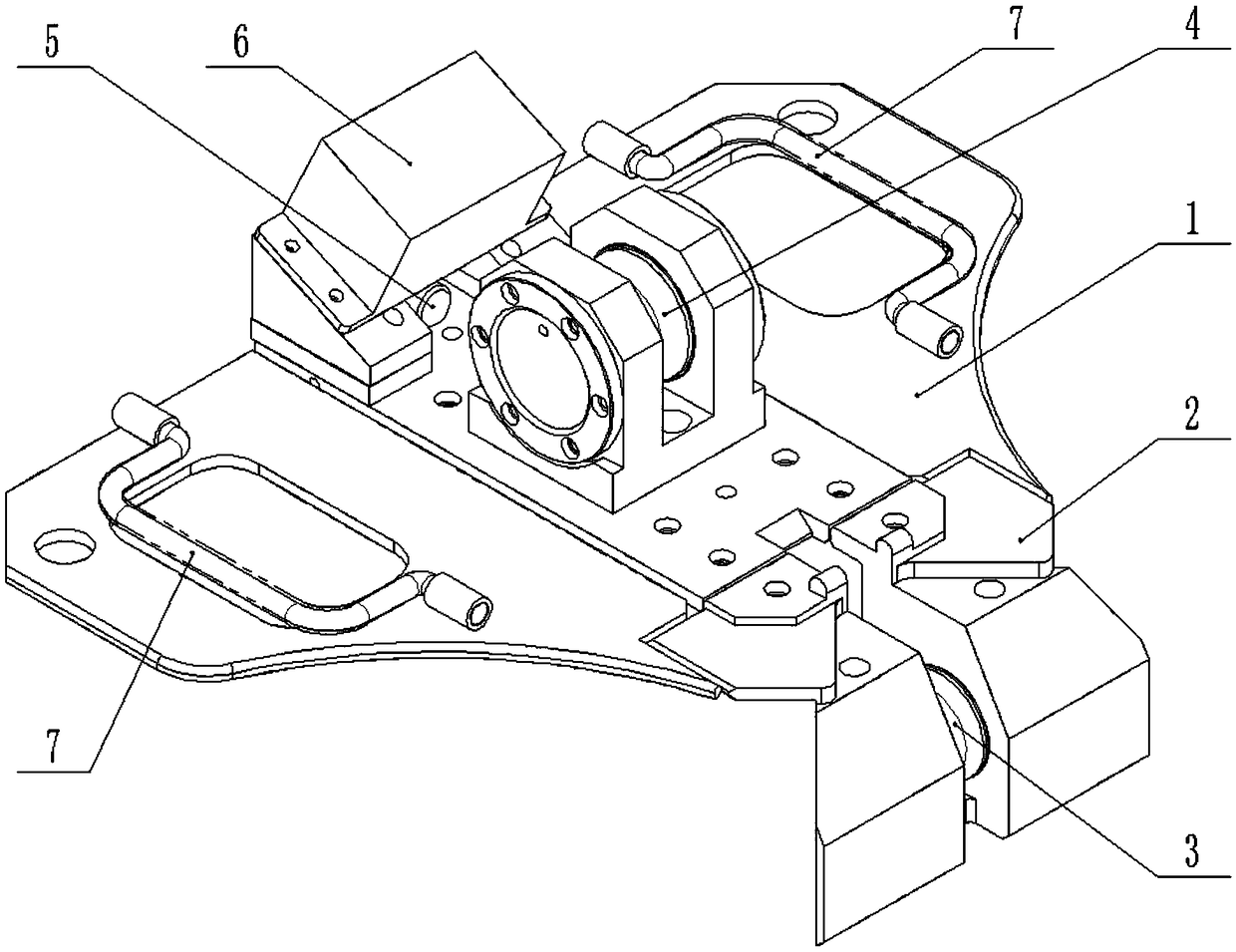
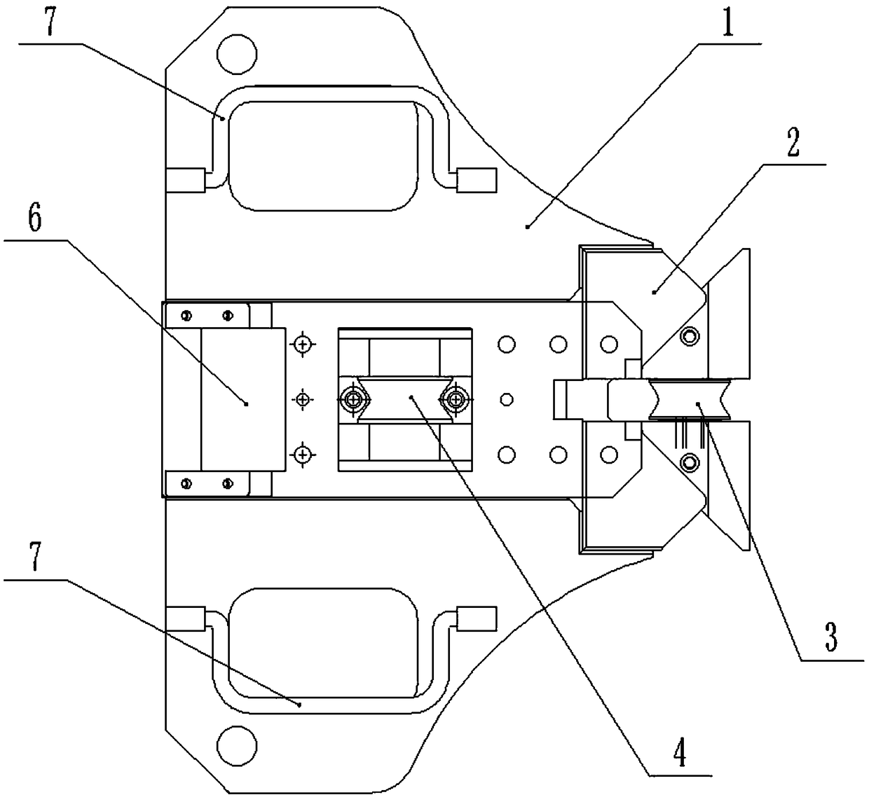
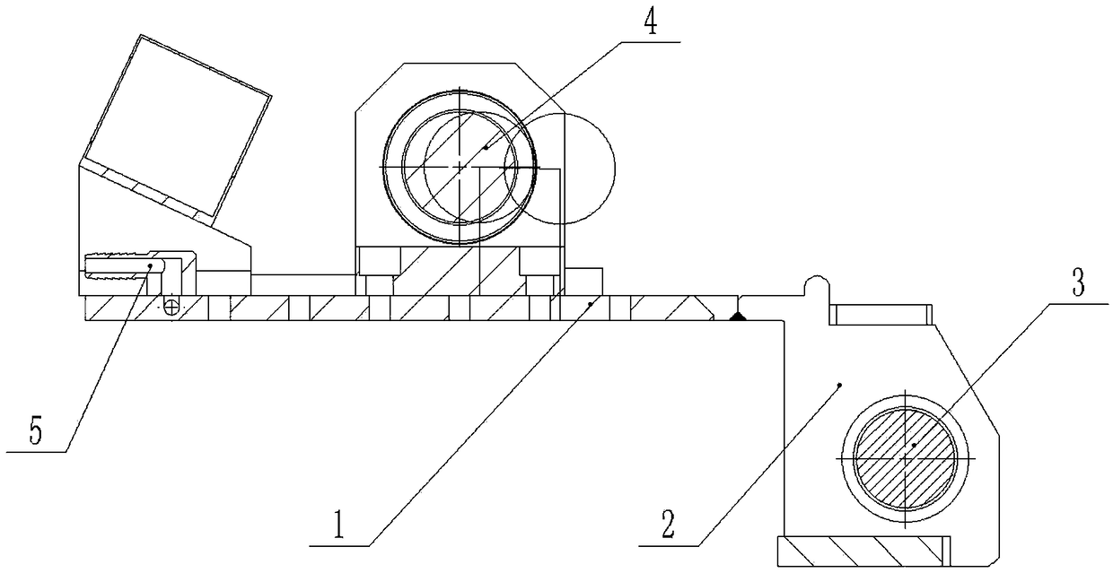
[0025] Combine below figure 1 , 2 , 3, 4 illustrate the present embodiment, a kind of horizontal well cable protection device, comprises the pulley frame 1 outside the well, the pulley frame 2 in the well, the pulley 3 in the well and the pulley 4 outside the well, the pulley frame 1 outside the well and the pulley frame 2 in the well Fixedly connected, the lower end of the pulley frame 2 in the well is a triangular structure cooperating with the corners of the wellhead, the pulley 3 in the well is connected to the pulley frame 2 in the well in rotation, and the pulley 4 outside the well is connected to the pulley frame outside the well in rotation 1. When in use, one end of the cable is connected to the traction device, and the other end of the cable extends into the well. The middle end of the cable is rolled and guided through the pulley 3 inside the well and the pulley 4 outside the well. This can not only avoid friction between the cable and the well wall, but also pass t...

specific Embodiment approach 2

[0026] Combine below figure 1 , 2 , 3, and 4 illustrate this embodiment, and this embodiment will further explain Embodiment 1. The two ends of the upper end surface of the pulley frame 1 outside the well are rotatably connected with a lifting handle 7, and the horizontal well cable protection device can be rotated to Vertical to the pulley frame 1 outside the well, when the lifting handle 7 is not in use, it can be rotated to fit with the pulley frame 1 outside the well.

specific Embodiment approach 3

[0027] Combine below figure 1 , 2 , 3, and 4 illustrate this embodiment, and this embodiment will further illustrate Embodiment 1. The left end of the outer pulley frame 1 is fixedly connected to a magnetic marker 6, and the magnetic marker 6, the inner pulley 3 and the outer pulley 4 In order to facilitate the measurement of the cable length, the connection of the downhole cable is usually equipped with an induction device for detecting the change of the electromagnetic signal. When the cable passes through the magnetic marker 6, the electromagnetic pulse changes, and the cable length is realized by capturing the electromagnetic pulse. The measurement; this part is the usual method for downhole cable length measurement, and the detection principle is the well-known electromagnetic induction principle, so this manual does not explain too much about the device model and principle.


PUM

PropertyMeasurementUnit
Bending angleaaaaaaaaaa

Abstract

The invention relates to the technical field of horizontal well cable protection, in particular to a horizontal well cable protection device and an application method. The horizontal well cable protection device comprises an outside well pulley bracket, an inside well pulley bracket, an an outside well pulley and an inside well pulley. The outside well pulley bracket and the inside well pulley bracket are fixedly connected. The lower end of the inside well pulley bracket is of a triangle structure connected with a well head edge corner in a matching mode. The inside well pulley is rotatably connected with the inside well pulley bracket. The outside well pulley is rotatably connected with the outside well pulley bracket. The left end of the outside well pulley bracket is fixedly connected with a magnetic marker. The center lines of the magnetic marker, the inside well pulley and the outside well pulley are positioned in the same plane. The left end of the outside well pulley bracket isfixedly connected with a compression air pipe. An air outlet of the compression air pipe is located between the magnetic marker and the outside well pulley. Friction loss of the cable can be lowered,the cable can be cleaned, cable corrosion can be avoided, and meanwhile influence on detection accuracy of the magnetic marker by metal impurities is avoided.

Description

technical field [0001] The invention relates to the technical field of horizontal well cable protection, in particular to a horizontal well cable protection device and a use method. Background technique [0002] In the horizontal well logging process, the wet joint logging process is usually used. After the cable is docked, it is connected to the ground instrument through the side pulley, the sky pulley and the ground pulley through the square bushing through the bypass outlet. Therefore, the cable is in direct contact with the wellhead side bushing, and friction occurs when the cable is running, causing wear to the cable and shortening the life of the cable; friction and scratches occur when the cable joint passes through, making the cable unable to pass smoothly, and the phenomenon of cable wire drawing occurs, which affects well logging schedule. [0003] For example, a logging cable protection device whose patent application number is CN201520715740.3 includes a main bo...

Claims


Application Information

Patent Timeline
IPC IPC(8): E21B47/00H02G11/00
CPCE21B47/00H02G11/00
Inventor 赵宪忠祝金磊单长城付鑫迟毅
Owner HEILONGJIANG LANDE ULTRASONIC TECH CO LTD
Why Eureka
Try Eureka