Hydraulic turbocharged engine with automatic start-stop

A turbocharger, engine technology, applied in the direction of engine components, combustion engines, engine control, etc., can solve the problems of increasing the cost, weight and complexity of vehicle systems

Pending Publication Date: 2018-11-13
FORD GLOBAL TECH LLC
View PDF2 Cites 3 Cited by
  • Summary
  • Abstract
  • Description
  • Claims
  • Application Information

AI Technical Summary

Problems solved by technology

In one example, the system described above requires the addition of a hydraulic pump motor of enormous size, which adds su

Method used


Image

  • Hydraulic turbocharged engine with automatic start-stop
  • Hydraulic turbocharged engine with automatic start-stop
  • Hydraulic turbocharged engine with automatic start-stop

Examples


Embodiment Construction

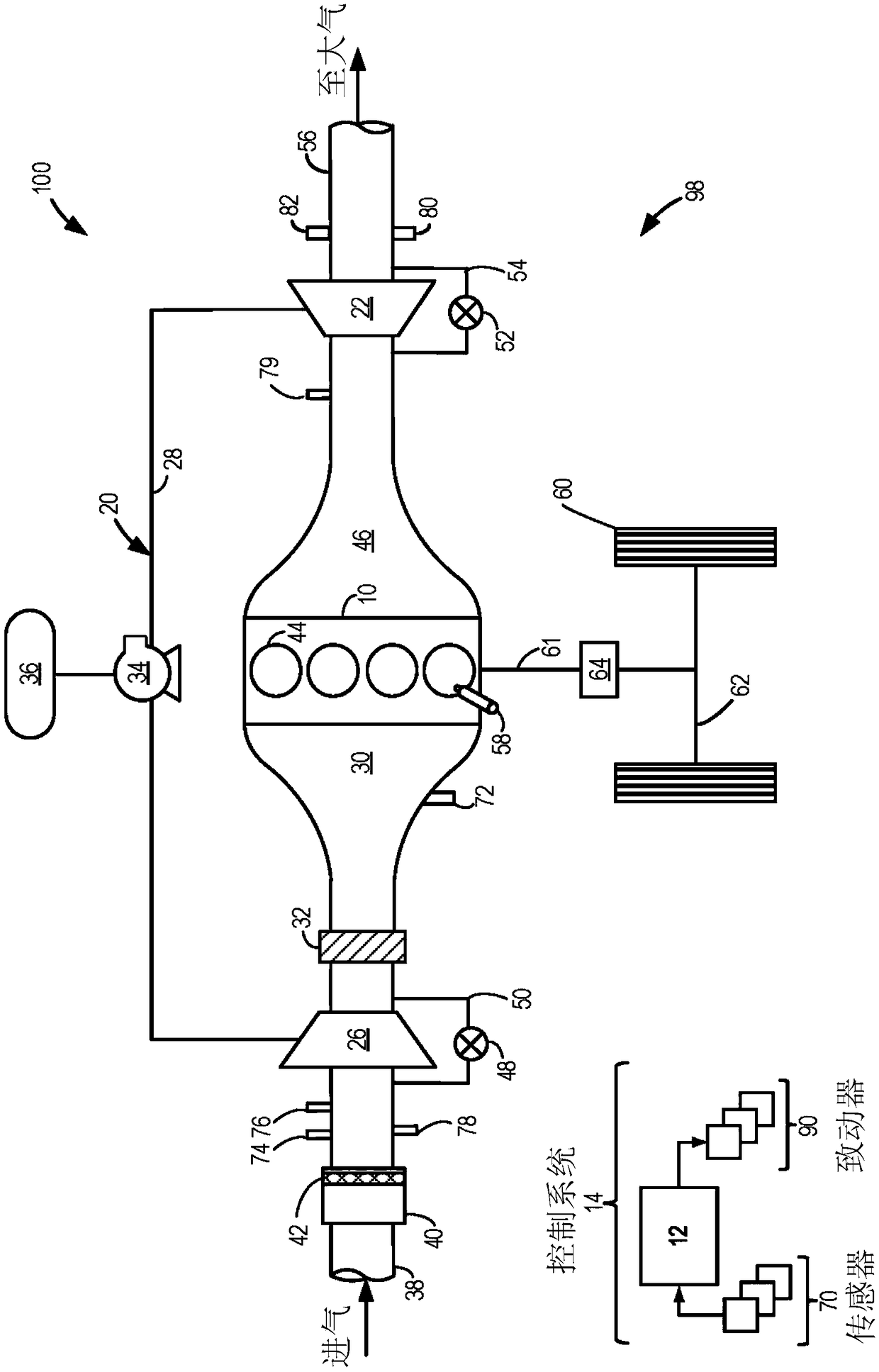
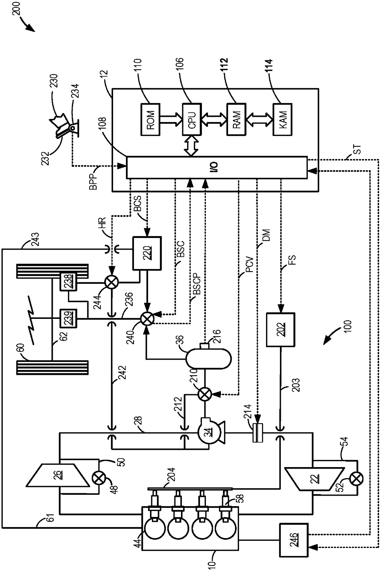
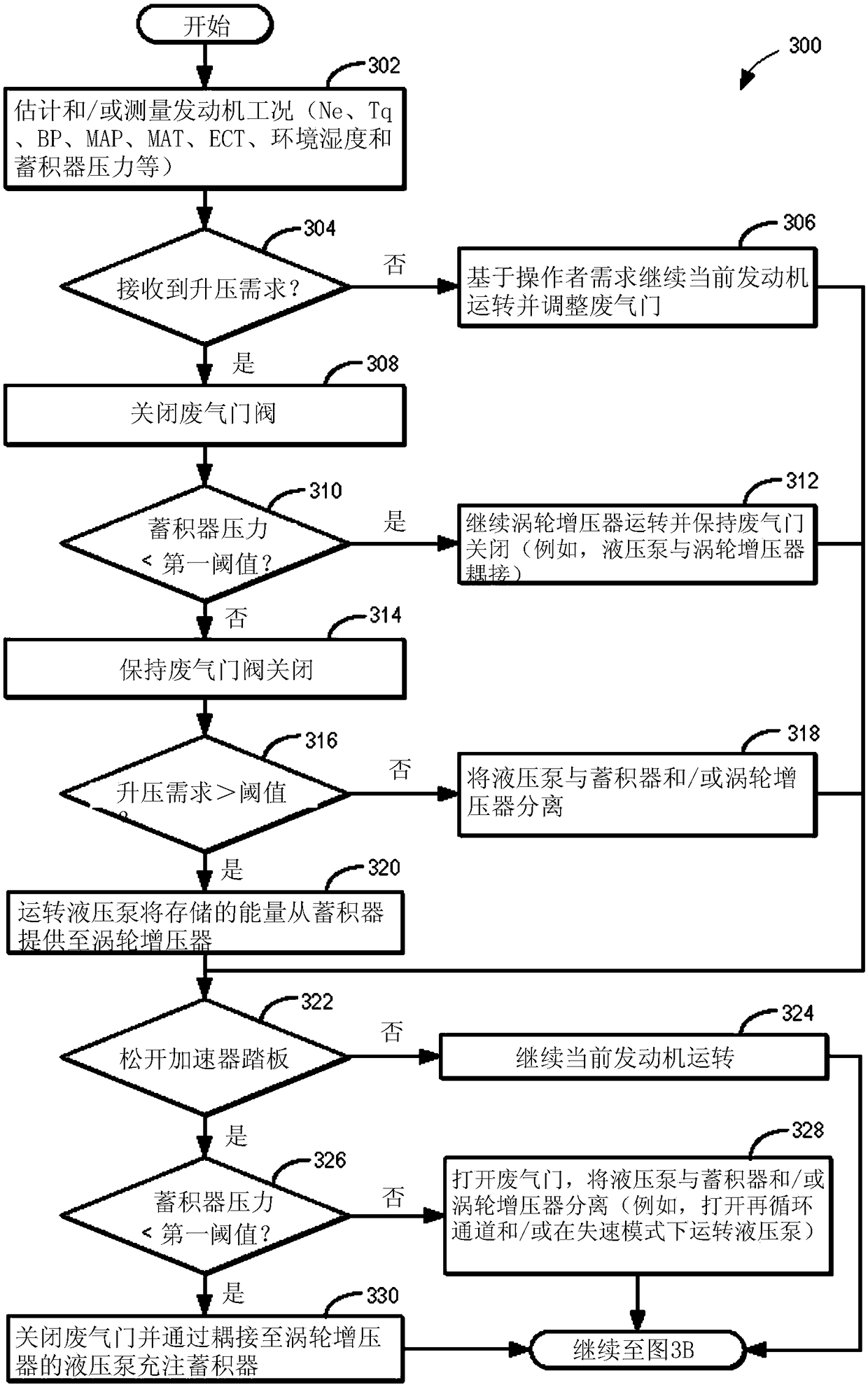
[0013] The following description relates to systems and methods for a hydraulic braking system that allows use of stop-start technology on hydraulic hybrid vehicles. An example of such a system includes a turbocharged engine, where the turbocharger is coupled to a hydraulic pump and accumulator, such as figure 1 shown. Where the accumulator may also be coupled to the vehicle's hydraulic braking system, and the hydraulic braking system may be configured to operate using hydraulic brake pressure from a main engine source or from the hydraulic accumulator, such as figure 2 shown. In one example, the engine may be a diesel (eg, compression ignition) engine, where the primary engine source may only supply hydraulic pressure to the hydraulic braking system when the engine is started and running. During engine operation, the controller program (eg, Figure 3A-Figure 3B example program shown) controls the hydraulic turbocharger. The vehicle controller may be configured to execute...


PUM


Abstract

The invention relates to a hydraulic turbocharged engine with automatic start-stop. Methods and systems are provided for a vehicle engine including a turbocharger coupled to a hydraulic pump and a hydraulic accumulator. In one example, a method may include, in response to the vehicle coming to a stop, supplying pressure to a hydraulic braking system of the vehicle from the accumulator coupled to ahydraulic pump coupled to a shaft of a turbocharger of an engine installed in the vehicle, and automatically shutting down the engine while the vehicle is stopped.

Description

technical field [0001] The present invention generally relates to methods and systems for hydraulic braking systems that allow the use of automatic engine start-stop technology on hydraulic hybrid vehicles. Background technique [0002] As emissions regulations continue to be introduced, the demand for more energy-efficient vehicles is also increasing. To improve fuel economy, technologies such as automatic start-stop systems are on the rise. These start-stop systems automatically shut down the engine by stopping fuel delivery to the combustion chamber when the vehicle is stopped and idling (a major source of fuel waste). Long periods of idling are typical for delivery vehicles, taxis and commuter vehicles in severe traffic jams. During a temporary engine shutdown, the engine restarts and resumes normal operation once the vehicle controller receives an indication from the operator of a torque request or other engine parameter requiring engine power (eg, low battery charge)...

Claims


Application Information

Patent Timeline
IPC IPC(8): F02B37/00B60K6/12F02D23/02
CPCB60K6/12B60K2006/126F02B37/00F02D23/02B60T17/02B60W30/18018B60W2510/0633F02B37/10F02B37/18F02D17/04F02D23/00F02D29/02F02D29/04F02D41/042F02N11/0822F02N11/0833F02N2200/0801F02N2200/0807F02N2200/101Y02T10/12Y02T10/40B60T2270/88
Inventor B·L·富尔顿D·R·汉纳
Owner FORD GLOBAL TECH LLC
Why Eureka
Try Eureka