Novel horizontal gear and gear rack engine

A technology of rack and pinion, engine, applied in machine/engine, gear lubrication/cooling, belt/chain/gear, etc., can solve the problem of reducing energy output efficiency, high structural strength requirements of connecting rod and crank, connecting rod and crank Excessive structural pressure and other problems, to achieve the effect of overcoming the problem of knocking the cylinder

Inactive Publication Date: 2018-11-13
ZHEJIANG UNIV
View PDF8 Cites 0 Cited by
  • Summary
  • Abstract
  • Description
  • Claims
  • Application Information

AI Technical Summary

Problems solved by technology

However, the crank-link mechanism of the traditional engine has great structural defects. When the engine completes the compression stroke and starts the power stroke, when the connecting rod and the piston are on a straight line, the piston is at the top dead center
Immediately afterwards, the combustible mixture burns to do work in the combustion chamber, and a large amount of energy is output instantaneously. At this time, the angle

Method used


Image

  • Novel horizontal gear and gear rack engine
  • Novel horizontal gear and gear rack engine
  • Novel horizontal gear and gear rack engine

Examples


Embodiment

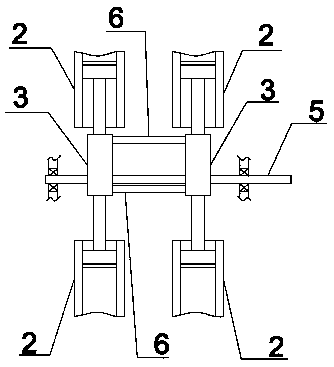
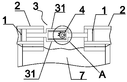
[0014] Such as figure 1 with figure 2 As shown, a novel horizontal rack and pinion engine includes a housing and an output shaft 5 that is rotatably connected with the housing. The output shaft 5 is sleeved with two transmission gears 4, and the transmission gear 4 is The central angle corresponding to the area covered by the gear teeth is 150°-180°, and the gear teeth of the two transmission gears 4 are located on the same side. The two transmission gears 4 correspond to the two transmission parts 3, that is, the four cylinders 2. If the intake and exhaust system of the engine is properly set, one of the four cylinders 2 is always in the power stroke, and then drives the other three cylinders 2 to complete the suction. Compared with the existing engine structure, the flywheel can be omitted and the system structure can be simplified.

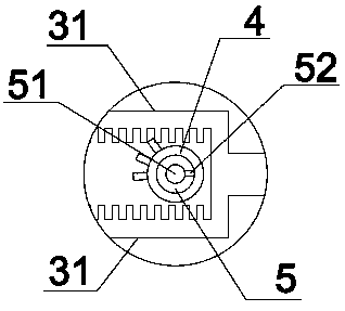
[0015] Such as figure 1 with figure 2 As shown, a transmission member 3 corresponding to the transmission gear 4 is also included, and t...


PUM

PropertyMeasurementUnit
Central angleaaaaaaaaaa

Abstract

The invention relates to the field of engines, and particularly discloses a novel horizontal gear and gear rack engine which comprises a shell and an output shaft, and further comprises transmission parts, wherein the output shaft is rotationally and movably connected with the shell; at least two transmission gears are arranged on the output shaft in a sleeving manner; the central angle to which the area covered by gear teeth on each transmission gear corresponds reaches 150-180 degrees; the transmission parts are in one-to-one correspondence with the transmission gears; pistons are correspondingly arranged on two sides of each transmission part; each transmission part comprises two gear racks matched with the corresponding transmission gear, and the two gear racks are parallel and arranged relative to the corresponding transmission gear in an upper-lower symmetric manner; and during the work, at most one gear rack is meshed with the corresponding transmission gear. According to the above novel horizontal gear and gear rack engine, the gear and gear rack transmission mode is adopted; the problem about dead points existing in a conventional engine structure is solved; and the engineoutput efficiency is improved.

Description

technical field [0001] The invention relates to a novel engine structure, in particular to a novel horizontal rack and pinion engine. Background technique [0002] The engine is a device that converts the heat energy generated by fuel combustion into mechanical energy, and is the power source of the car. The traditional engine converts the reciprocating linear motion of the piston into the rotary motion of the crank through the crank connecting rod mechanism, and then outputs the energy through the output shaft. In the power stroke, the engine converts the heat energy generated by fuel combustion into the mechanical energy that pushes the piston to reciprocate, and then drives the crankshaft to rotate through the connecting rod; in the other three strokes, the energy stored by the flywheel in the power stroke Drive the piston for reciprocating motion. However, the crank-link mechanism of the traditional engine has a great structural defect. When the engine completes the co...

Claims


Application Information

Patent Timeline
IPC IPC(8): F02B61/06F16H19/04F16H57/04
CPCF02B61/06F16H19/043F16H57/04F16H57/042F16H57/045F16H57/0475
Inventor 熊树生马泽群尹耀辉易善强邓鸿洋
Owner ZHEJIANG UNIV
Why Eureka
Try Eureka