Bidirectional buffer speed adjustable hydraulic oil cylinder

A two-way buffer, hydraulic cylinder technology, applied in the field of hydraulic cylinders, can solve the problems of additional damage to mechanical equipment, increase the installation space of the cylinder, reduce the mechanical life and other problems, and achieve the effect of wide range of use, simple structure and strong applicability

Pending Publication Date: 2018-11-13
CHANGZHI QINGHUA MACHINERY FACTORY +1
View PDF9 Cites 2 Cited by
  • Summary
  • Abstract
  • Description
  • Claims
  • Application Information

AI Technical Summary

Problems solved by technology

[0002] If the working mechanism driven by the hydraulic actuator cylinder is fast or has a large holding capacity, if it stops suddenly or changes direction, it will cause mechanical collision, generate large vibration shock and noise, and bring additional damage to the entire mechanical equipment. It reduces the mechanical life and increases the environmental pollution. In order to reduce or eliminate the impact, it is necessary for the cylinder to take certain measures at the end of the stroke to realize the speed decrease until it reaches zero.
[0003] At present, the commonly used methods are: through the design of the hydraulic system, adding a buffer circuit on the oil circuit, and adding a sensor on the cylinder to achieve buffering; by setting a rectangular or triangular buffer groove at the end of the cylinder retraction stroke, and setting a corresponding one on the end face of the piston rodless cavity. This type of buffer is limited by the structure, and only one end can be retracted for buffering, and the buffer structure of the check valve is added. Usually, the structure of the check valve is external, which changes the traditional structure of the oil cylinder, increases the volume of the oil cylinder, and increases Cylinder installation space

Method used


Image

  • Bidirectional buffer speed adjustable hydraulic oil cylinder
  • Bidirectional buffer speed adjustable hydraulic oil cylinder

Examples


Embodiment Construction

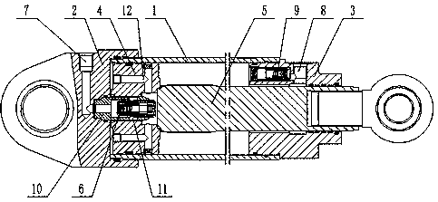
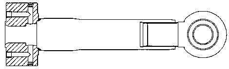
[0020] Such as figure 1 , figure 2 As shown, the hydraulic oil cylinder with adjustable bidirectional buffer speed of the present invention includes a cylinder body 1, a cylinder bottom 2 is arranged at one end of the cylinder body 1, a cylinder head 3 is arranged at the other end, a piston 4 and a piston rod connected with the piston 4 are arranged inside 5. One end of the piston 4 is opposite to the cylinder bottom 2 to form a rodless cavity, the other end of the piston 4 is connected to the piston rod 5 to form a rod cavity in the cylinder body 1, and the side of the piston 4 opposite to the cylinder bottom 2 is provided with a piston concave hole. The side of the cylinder bottom 2 opposite to the piston 4 is provided with a cylinder bottom concave hole corresponding to the piston concave hole, a first check valve 6 is arranged in the cylinder bottom concave hole, a first liquid inlet 7 is arranged on the cylinder bottom 2, and the first The liquid inlet 7 is connected wi...


PUM


Abstract

The invention discloses a bidirectional buffer speed adjustable hydraulic oil cylinder, and belongs to the field of hydraulic cylinders. According to the technical aims to be achieved, the shape of the oil cylinder is not changed, the size and mounting space of the oil cylinder are not increased, the structure is simple, and the bidirectional buffer speed is adjustable through the hydraulic oil cylinder. According to the technical scheme adopted for achieving the technical aims, the bidirectional buffer speed adjustable hydraulic oil cylinder comprises a cylinder body; a piston and a piston rod are arranged in the cylinder body; a throttling channel is arranged on the side, back onto the piston rod, of the piston, and a first one-way valve is arranged in the middle and connected with a rodless cavity oil inlet; a rod cavity oil inlet and a second one-way valve are arranged at the rear end of the piston rod; a thickened segment is arranged on the piston rod and provided with an oil leaking groove; and the piston rod is controlled to stretch out and retract through the one-way valves, and the stretching-out and retracting speed is controlled through the throttling channel and the oilleaking groove. The bidirectional buffer speed adjustable hydraulic oil cylinder can be widely applied to the field of hydraulic cylinders.

Description

technical field [0001] The invention relates to a hydraulic oil cylinder with adjustable bidirectional buffering speed, which belongs to the technical field of hydraulic cylinders. Background technique [0002] If the working mechanism driven by the hydraulic actuator cylinder is fast or has a large holding capacity, if it stops suddenly or changes direction, it will cause mechanical collision, generate large vibration shock and noise, and bring additional damage to the entire mechanical equipment. The mechanical life is reduced, and the environmental pollution is increased. In order to reduce or eliminate the impact, it is necessary for the cylinder to take certain measures at the end of the stroke to achieve a gradual decrease in speed until it reaches zero. [0003] At present, the commonly used methods are: through the design of the hydraulic system, adding a buffer circuit on the oil circuit, and adding a sensor on the cylinder to achieve buffering; by setting a rectang...

Claims


Application Information

Patent Timeline
Patent Type & Authority Applications(China)
IPC IPC(8): F15B15/22
CPCF15B15/222F15B2215/30
Inventor 武丽明袁晓峰韩晓马雷鹏骆新营常军王锐敏
Owner CHANGZHI QINGHUA MACHINERY FACTORY
Why Eureka
Try Eureka