Induction cooker and interface display control method of induction cooker
A control method and interface control technology, which can be applied to household stoves/stoves, electric heating fuel, lighting and heating equipment, etc., and can solve the problems of low functional integration of induction cookers
- Summary
- Abstract
- Description
- Claims
- Application Information
AI Technical Summary
Problems solved by technology
Method used
Image

Examples
Embodiment 1
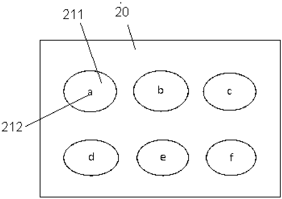
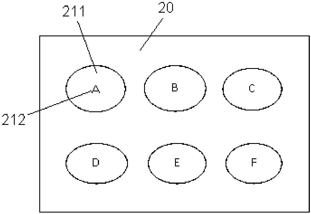
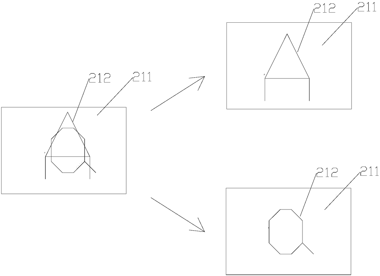
[0100] The cooking utensil has a trigger, and the utensil type detection element includes a trigger switch. The cooking utensil is placed in the induction cooker, and after the trigger switch is triggered by the trigger, the trigger switch sends a corresponding utensil type signal. That is to say, a raised structure can be provided on the cooking utensil as a trigger, and a trigger switch cooperating with the trigger is provided in the induction cooker. When the cooking utensil is placed in place, the trigger can press the trigger switch, and the matching is successful. The trigger switch will send the corresponding appliance type signal, so that the corresponding interface control module is invoked.
Embodiment 2
[0102] The cooking utensil has an induction element, and the utensil type detection element includes an induction switch. The cooking utensil is placed in the induction cooker, and after the induction switch and the induction element sense, the induction switch sends a corresponding utensil type signal. Different induction elements can be installed on pots and cups of different sizes, and the induction switch can correspondingly detect the interface control module and control program that should be called by the cooking utensil according to the different induction elements, so as to improve the automation degree of the induction cooker.
[0103] Example 1: An induction element is installed on the pot, the induction element is a magnetic device, a magnetic induction switch is installed on the pot body, the type of cooking utensil is determined through magnetic induction, and the corresponding interface control module is invoked.
[0104] Example 2: The pot is equipped with a res...
Embodiment 3
[0106] The cooking appliance has a microcontroller with a built-in wireless module. The appliance type detection element includes a wireless receiving module. The microcontroller in the cooking appliance can set the marking program wirelessly. The marking program records the appliance type signal to trigger the corresponding interface control. module is called. That is to say, the utensil type signal is stored in the microcontroller of the cooking utensil, and the utensil type signal can be modified. And the microcontroller communicates with the control unit 40 of the induction cooker, so that the corresponding interface control module can be invoked. Since different control programs are recorded in different interface control modules, the interface displays are also different according to different control programs.
[0107] Optionally, the above-mentioned cooking utensils include one or more of a hot pot, a soup pot, a frying pan, a kettle, and a pressure cooker. When the ...
PUM
 Abstract
Description
Claims
Application Information
 - R&D
- Intellectual Property
- Life Sciences
- Materials
- Tech Scout
- Unparalleled Data Quality
- Higher Quality Content
- 60% Fewer Hallucinations
Browse by: Latest US Patents, China's latest patents, Technical Efficacy Thesaurus, Application Domain, Technology Topic, Popular Technical Reports.
© 2025 PatSnap. All rights reserved.Legal|Privacy policy|Modern Slavery Act Transparency Statement|Sitemap|About US| Contact US: help@patsnap.com