[0022] The technical solutions in the embodiments of the present invention will be clearly and completely described below in conjunction with the accompanying drawings in the embodiments of the present invention. Obviously, the described embodiments are only a part of the embodiments of the present invention, rather than all the embodiments. Based on the embodiments of the present invention, all other embodiments obtained by those of ordinary skill in the art fall within the protection scope of the present invention.
[0023] According to an embodiment of the present invention, an air purifier that facilitates dust removal is provided.
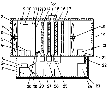
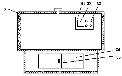
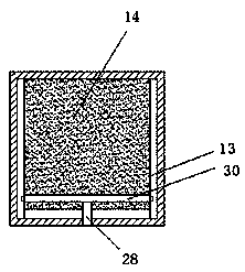
[0024] Such as Figure 1-3 As shown, an air purifier for facilitating dust removal according to an embodiment of the present invention includes an air purifier body 8 and a bottom box 2. One side of the air purifier body 8 is provided with an air inlet channel 7. An inlet fan 6 is fixedly installed on one side of the passage 7, an air quality detection chamber 9 is provided on one side of the inlet fan 6, and a particulate matter detector 10 is fixedly installed on the top of the air quality detection chamber 9, and the air quality detection chamber An air component detector 4 and a temperature and humidity sensor 5 are fixedly installed at the bottom of the air quality detection room 9, an automatic valve 11 is provided on one side of the air quality detection room 9, and an air purification room 12 is provided on one side of the air quality detection room 9; One end of the inner cavity of the air purification chamber 12 is symmetrically fixed with a sliding rod 13, a cleaning rod 30 is slidably connected between the two sliding rods 13, and a hydraulic cylinder 28 is fixedly connected to the middle of the cleaning rod 30. The hydraulic cylinder 28 It is fixedly installed at the bottom of the inner cavity of the bottom box 2, a side surface of the hydraulic cylinder 28 is fixedly connected with an oil pipe 29, and an end of the oil pipe 29 away from the hydraulic cylinder 28 is fixedly connected with an oil tank 1. An oil pump 3 is fixedly installed on the top, and one side of the cleaning rod 30 is sequentially fixedly installed with a primary filter 14, an activated carbon filter 36, a HEPA high efficiency filter 16, and a photocatalyst purification network 17, the primary filter 14, activated carbon The top of the filter 36, the HEPA high-efficiency filter 16, and the photocatalyst purification net 17 are all connected with a vibrator 15; the bottom of the inner cavity of the air purification room 12 is fixedly installed with a dust hood 25, and the bottom of the dust hood 25 is fixedly connected There is a dust suction pipe 26, and the end of the dust suction pipe 26 away from the dust suction hood 25 is fixedly connected with a dust remover 27, and the dust remover 27 is fixedly installed at the bottom of the inner cavity of the bottom box 2. Vibration can cause the filter to vibrate, thereby effectively shaking off the contaminants trapped in the filter. The cleaning rod 30 can brush off the thicker dust and particles on the primary filter, and the fallen dust or pollution The dust is sucked in by the dust hood 25 and cleaned by the dust collector 27. The structure is reasonable and can effectively remove dust without damaging the filter. The service life of the filter is prolonged and the purification effect of the air purifier is improved. An exhaust fan 18 is provided on one side of the purification net 17, a plasma generator 20 is provided on one side of the exhaust fan 18, an air outlet 19 is opened at the right end of the air purifier body 8, and the bottom right end of the inner cavity of the bottom box 2 A humidifier 24 is fixedly installed, and the top of the humidifier 24 is fixedly connected with a humidification tube 22, and the humidification tube 22 penetrates the bottom of the air purifier body 8 and is fixedly connected with a spray head 21, and the spray head 21 is arranged at One side of the air outlet 19 can increase indoor humidity while purifying the air. A control panel 31 is fixedly installed on the upper part of the front of the air purifier body 8, and one end of the control panel 31 is provided with a display Screen 32, the other end of the surface of the control panel 31 is provided with a control button 33, the control panel 31 and the inlet fan 6, the particulate matter detector 10, the air component detector The detector 4, the temperature and humidity sensor 5, the automatic valve 11, the plasma generator 20, the oil pump 3, and the humidifier 24 are all electrically connected. The front of the bottom box 2 is fixedly installed with an inspection door 34, and the bottom of the bottom box 2 An anti-skid pad 23 is fixedly connected.
[0025] In specific applications, for the cleaning rod, the cleaning rod 30 is provided with cleaning bristles on the side close to the primary filter screen. For the dust suction hood 25, the number of the dust suction hood 25 is five, and Five dust suction hoods 25 are arranged in parallel. For the display screen 32, the display screen 32 is a liquid crystal display screen, and the surface of the display screen 32 is provided with an anti-scratch film. For the maintenance door 34, the maintenance The door 34 is provided with a handle 35 to facilitate the inspection and maintenance of the inside of the bottom box 2. For the air outlet 19, the angle between the air outlet 19 and the horizontal plane is 30 degrees. For the air inlet channel 7, the air inlet The wind channel 7 is a curved channel, and the number of the air inlet channels 7 is at least six, which can make the air fully contact the detection equipment and reduce the detection error. For the particulate matter detector 10, the particulate matter detector 10 is PM2.5 Dust sensor, the air component detector 4 is a formaldehyde sensor, the particulate matter detector 10 is a PM2.5 dust sensor, and the model is DSM501A, and the air component detector 4 is a formaldehyde sensor, and the model is CH20/S- 10. For the temperature and humidity sensor 5, the model of the temperature and humidity sensor 5 is YGM405, and for the vibrator 15, the model of the vibrator 15 is SY-2D.
[0026] In summary, with the above technical solutions of the present invention, by setting the vibrator 15, the dust hood 25, the dust pipe 26, the dust collector 27, the sliding rod 13, the cleaning rod 30, the hydraulic cylinder 28 and the control button 33, When the equipment needs to clean up the dust, turn on the vibrator 15, the dust remover 27 and the hydraulic cylinder 28 through the control button 33. The vibration of the vibrator 15 can cause the filter to vibrate, thereby effectively absorbing the trapped pollutants in the filter. When it falls, the cleaning rod 30 can brush down the thicker dust and particles on the primary filter. The fallen dust or pollutants are sucked by the dust collector 25 and cleaned by the dust collector 27. The structure is reasonable and can effectively clean. It does not cause damage to the filter, prolongs the service life of the filter, and improves the purification effect of the air purifier. By setting the spray head 21, the humidification pipe 22, and the humidifier 24, the air can be purified while increasing Indoor humidity.
[0027] The above descriptions are only the preferred embodiments of the present invention and are not intended to limit the present invention. Any modification, equivalent replacement, improvement, etc. made within the spirit and principle of the present invention shall be included in the present invention. Within the scope of protection.