Method for measuring physical yielding point position and stress level of component

A technology of stress level and measurement method, applied in the direction of applying stable tension/pressure to test the strength of materials, measuring devices, instruments, etc., can solve the problem that the performance of component points is difficult to give detailed results, so as to improve the overall performance, Good practicality, easy to use effect

Inactive Publication Date: 2018-11-13
AVIC BEIJING AERONAUTICAL MFG TECH RES INST
10 Cites 0 Cited by

AI-Extracted Technical Summary

Problems solved by technology

[0006] In view of the characteristics of the general static load tensile test instrument, it only records the overall stress-strain curve of the component, which gives sufficient mechanical...

Method used

Further, the first step, design and make component, component design also will reduce heat loss, for example adopt hole component, reduce the heat loss that clamping brings except according to national standard rule; Second step, in The conventional tensile test is carried out on the static load tensile machine, and the infrared thermal images of the components are taken and recorded during the whole process of the test. The shooting speed is higher than the sampling speed selected for the static load tensile test; the third step is based on the recorded The fracture time of the component in the infrared thermal image and the load/time data table recorded by the static load tensile test system are synchronized on the time axis of the two, and an accurate correlation between the infrared thermal image and the load is established accordingly; the fourth step is to The physical yield point and the position of the physical yield point of the component are defined in the effective measurement segment of the continuously recorded infrared thermal image of the component.
Fur...

Abstract

The invention provides a method for measuring the physical yielding point position and the stress level of a component. The method is technically characterized in that thermal image shooting is performed on the component in the static load tension test process, and the physical yielding point position and the stress level of the thin-plate component are accurately measured based on synchronous load and component temperature field data. Relatively accurate physical yielding point position and stress can be acquired, and more accurate mechanical property reference data are provided for welding joint design and performance evaluation. As the position firstly with yielding is the weakest position in a structure, the method can be applied to structural static load test to accurately locate theweak position, overall performances are improved for design, and the problem of insufficient precision of a current macroscopic shielding strength measuring method based on a stress-strain curve is solved. The method is simple to use, easy to implement and excellent in practicability, and original static load tension test is not changed.

Application Domain

Material strength using tensile/compressive forces

Technology Topic

PhysicsStress level +5

Image

  • Method for measuring physical yielding point position and stress level of component
  • Method for measuring physical yielding point position and stress level of component
  • Method for measuring physical yielding point position and stress level of component

Examples

  • Experimental program(2)

Example Embodiment

[0031] Example 1
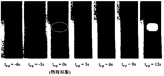
[0032] A method for determining the physical yield point position and stress level of a member. In the process of static load tensile test, infrared thermal imaging of the member is taken, and based on the synchronized load and member temperature field data, the physical yield point position and stress level of the thin plate member are determined. Stress levels are accurately measured.
[0033] Further, the first step is to design and manufacture the components. In addition to the national standards, the component design should also reduce heat loss, such as using hole components to reduce the heat loss caused by clamping; the second step, in the static load tension The conventional tensile test is carried out on the tensile machine, and the infrared thermal image of the component is photographed and recorded during the whole test process, and the shooting speed is higher than the sampling speed selected for the static load tensile test; the third step is based on the recorded infrared thermal image. The fracture time of the middle member and the load/time data table recorded by the static load tensile test system are synchronized with the time axis of the two, and the precise correlation between the infrared thermal image and the load is established accordingly; The physical yield point and the position of the physical yield point of the component are defined in the valid measurement segment of the component thermal image.
[0034] Further, the test environment in the second step is the ambient temperature change value ±0.2°C/h, the air flow rate is less than 50mm/s, and the ambient light wavelength 1μm irradiance change amount is less than 1‰ during the test process.
[0035] Further, in the fourth step, the method of defining the physical yield point and the position of the physical yield point of the component is to first take the temperature/time curve of the center point of the component in the effective measurement section of the continuously recorded component infrared thermal image, and determine the temperature from The rough time period of descending to ascending, and then the image is calculated in detail during this time period to find the target area. The size of the target area is set by itself according to the thickness and size of the component. For the transition that continuously exceeds 6 points, the time point is defined as the physical yield point, the corresponding load is the load when physical yield occurs, and the position of the target area on the component is the position of the physical yield point of the component.

Example Embodiment

[0036] Example 2
[0037] A method for determining the physical yield point position and stress level of a member. In the process of static load tensile test, infrared thermal imaging of the member is taken, and based on the synchronized load and member temperature field data, the physical yield point position and stress level of the thin plate member are determined. Stress levels are accurately measured.
[0038]Further, the first step is to design and manufacture the components. In addition to the national standards, the component design should also reduce heat loss, such as using hole components to reduce the heat loss caused by clamping; the second step, in the static load tension The conventional tensile test is carried out on the tensile machine, and the infrared thermal image of the component is photographed and recorded during the whole test process, and the shooting speed is higher than the sampling speed selected for the static load tensile test; the third step is based on the recorded infrared thermal image. The fracture time of the middle member and the load/time data table recorded by the static load tensile test system are synchronized with the time axis of the two, and the precise correlation between the infrared thermal image and the load is established accordingly; The physical yield point and the position of the physical yield point of the component are defined in the valid measurement segment of the component thermal image.
[0039] Further, the test environment in the second step is the ambient temperature change value ±0.2°C/h, the air flow rate is less than 50mm/s, and the ambient light wavelength 3μm radiation illuminance change during the test process is less than 1‰.
[0040] Further, in the fourth step, the method of defining the physical yield point and the position of the physical yield point of the component is to first take the temperature/time curve of the center point of the component in the effective measurement section of the continuously recorded component infrared thermal image, and determine the temperature from A rough time period of descending to ascending, then the image is calculated in detail during that time period, looking for the target area, the size of the target area is 0.5-1.5 times the thickness, and the average temperature of the target area first occurs from constant to continuously exceeding 6 For the transition of point rise, the corresponding load is the load when physical yielding occurs, and the position of the target area on the member is the position of the physical yield point of the member.
[0041] The algorithm used in the above embodiment may be the software provided with the infrared thermal imager, or other image calculation software or self-programming may be used for optimization calculation. In short, it is a common algorithm in the field of image processing. This embodiment adopts the regional temperature mean value algorithm performed by the software of the infrared thermal imager. According to the thickness of the component, the thermal conductivity of the material, the loading rate and the temperature measurement accuracy of the infrared thermal imager, the regional average temperature of the 50Hz infrared thermal image frame rate was selected for calculation.
[0042] The results are as figure 1 shown.

PUM

no PUM

Description & Claims & Application Information

We can also present the details of the Description, Claims and Application information to help users get a comprehensive understanding of the technical details of the patent, such as background art, summary of invention, brief description of drawings, description of embodiments, and other original content. On the other hand, users can also determine the specific scope of protection of the technology through the list of claims; as well as understand the changes in the life cycle of the technology with the presentation of the patent timeline. Login to view more.

Similar technology patents

Method and apparatus for implementing resource scheduling

ActiveCN101488908AImprove business feelimprove overall performance
Owner:HUAWEI TECH CO LTD

Silk-screen printing method for positive electrode of solar battery

ActiveCN102689534AAvoid electrical performance degradationimprove overall performance
Owner:JETION SOLAR HLDG

Classification and recommendation of technical efficacy words

  • improve overall performance
  • easy to use

High-precision distributed pulse signal time difference of arrival detection system

ActiveCN102023290AReduce target positioning errorimprove overall performance
Owner:THE SECOND RES INST OF CIVIL AVIATION ADMINISTRATION OF CHINA

Mass small file processing method based on HDFS

InactiveCN105404652AImprove write and read efficiencyimprove overall performance
Owner:HOHAI UNIV

A satellite call access control method

InactiveCN101106417AImprove onboard resource utilizationimprove overall performance
Owner:BEIHANG UNIV

Laser assisted total joint arthroplasty

InactiveUS20090234360A1easy to use
Owner:ALEXANDER VLADIMIR

Enclosure for a portable hemodialysis system

ActiveUS20090114582A1easy to use
Owner:DEKA PROD LLP
Why Eureka
Try Eureka