
Core displacement device capable of realizing synchronous evaluation of oil displacement effect

A technology of core displacement and oil displacement, which is applied in the direction of material inspection, soil material testing, etc., can solve the problems of prolonging the experimental development cycle, increasing economic costs, and being unable to simultaneously evaluate the pros and cons of various schemes, so as to shorten the evaluation cycle, The effect of stabilizing liquid inlet and reducing economic and space costs

Inactive Publication Date: 2018-11-13
SOUTH CHINA UNIV OF TECH
View PDF7 Cites 3 Cited by
  • Summary
  • Abstract
  • Description
  • Claims
  • Application Information

AI Technical Summary

Problems solved by technology

However, the existing experimental instruments are generally unable to simultaneously evaluate the advantages and disadvantages of multiple schemes, and have only one function, such as conducting research on core permeability measurement and formation damage evaluation (core sensitivity) under the conditions of simulated formation pressure and formation temperature , which will not only prolong the experimental development cycle, but also increase the economic cost of the experiment and bring a lot of inconvenience

Method used


Image

  • Core displacement device capable of realizing synchronous evaluation of oil displacement effect
  • Core displacement device capable of realizing synchronous evaluation of oil displacement effect
  • Core displacement device capable of realizing synchronous evaluation of oil displacement effect

Examples


Embodiment 1

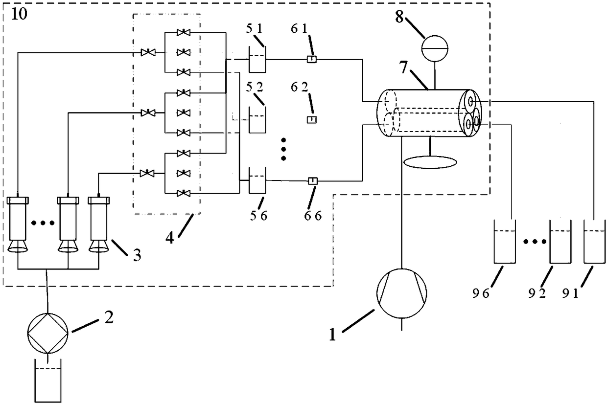
[0028] Such as figure 1 As shown, a core displacement device capable of synchronously evaluating the oil displacement effect includes: a water injection system, a core holder 7, a confining pressure pump 1, a pressure gauge 8, a constant temperature box 10 and a collection device,

[0029] The water injection system includes a non-pulse pump 2, six liquid storage tanks 3 arranged in the thermostat, a valve adjustment system 4, six buffer tanks and six liquid flowmeters, and the inlets of each liquid storage tank 3 are It is connected to the output end of the non-pulse pump 2, and the outlet of each liquid storage tank 3 is respectively connected to the corresponding buffer tank and the inner cavity input end of the core holder 7 through the valve adjustment system 4;

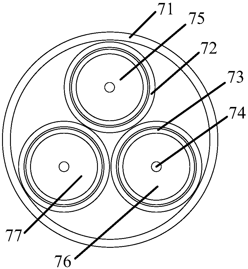
[0030] The core holder 7 is a cylindrical sealed structure placed in the constant temperature box, which includes three inner cavities for placing the core, the bottom of the core holder 7 is connected to the co...

Embodiment 2

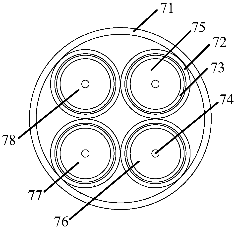
[0041] Such as image 3 As shown, the difference between this embodiment and Embodiment 1 is that the core holder 7 includes a cylindrical outer wall 71 with both ends sealed, and the outer wall 71 is provided with a rubber sleeve of the holder as a cavity wall 72 Form 4 inner cavities that do not interfere with each other, namely: cavity No. 1 75, cavity No. 2 76, cavity No. The middle part is respectively provided with a liquid inlet port 74 and an outlet port. The first cavity 75 , the second cavity 76 , the third cavity 77 and the fourth cavity 78 are uniformly arranged in a circular shape in the cylindrical outer wall 71 .

[0042] In this embodiment, the synchronous evaluation and oil displacement effect detection of four rock cores can be realized at the same time. In order to facilitate the installation of rock cores, the two sealing ends of the outer wall 71 are provided with four threaded holes and threaded plugs whose diameters match the inner cavity. The center o...

Embodiment 3

[0044] Such as Figure 4As shown, the difference between this embodiment and Embodiment 1 is that the core holder 7 includes a cylindrical outer wall 71 with both ends sealed, and the outer wall 71 is provided with a rubber sleeve of the holder as a cavity wall 72 Form 5 inner cavities that do not interfere with each other, namely: No. 1 cavity 75, No. 2 cavity 76, No. 3 cavity 77, No. 4 cavity 78, and No. 5 cavity 79, and plugs 73 are provided at both ends of the rubber sleeves of each holder , The middle parts of the two plugs are respectively provided with a liquid inlet port 74 and an outlet port. The first cavity 75 , the second cavity 76 , the third cavity 77 , the fourth cavity 78 and the fifth cavity 79 are uniformly arranged in a circular shape in the cylindrical outer wall 71 .

[0045] In this embodiment, the synchronous evaluation and oil displacement effect detection of five rock cores can be realized at the same time. In order to facilitate the installation of r...


PUM

PropertyMeasurementUnit
volumeaaaaaaaaaa
volumeaaaaaaaaaa

Abstract

The invention discloses a core displacement device capable of realizing synchronous evaluation of an oil displacement effect. The core displacement device comprises a water injection system, a core clamping device, a confining pressure pump, a pressure gauge, a constant-temperature box and a collection device, wherein the water injection system comprises a pulse-free pump, a plurality of liquid storage tanks arranged in the constant-temperature box, a valve regulation system, a plurality of buffering tanks and a liquid flow meter; an inlet of each liquid storage tank is connected with an output end of the pulse-free pump; an outlet of each liquid storage tank is connected with the corresponding buffering tank and an input end of an inner cavity of the core clamping device through the valveregulation system respectively; the core clamping device is of a barrel-shaped sealing structure placed in the constant-temperature box and the inner part of the core clamping device comprises a plurality of cavities for placing cores; the bottom of the core clamping device is connected with the confining pressure pump; the pressure gauge is connected onto the core clamping device through a thread. The core displacement device disclosed by the invention can be used for synchronously evaluating the oil displacement performance of several oil displacement agents, an evaluation period is shortened, the economic cost and the space cost are reduced and the accuracy of a result is high.

Description

technical field [0001] The invention relates to an oil field production experiment instrument, in particular to a core displacement device capable of synchronously evaluating the oil displacement effect. Background technique [0002] With the development of the oil industry, most oil fields have entered binary flooding, and some of them have also entered the high water cut period. Therefore, different oilfield production blocks will require different schemes. Therefore, this needs to be done before implementing different schemes. Laboratory experiments, especially core flooding experiments. However, the existing experimental instruments are generally unable to simultaneously evaluate the advantages and disadvantages of multiple schemes, and have only one function, such as conducting research on core permeability measurement and formation damage evaluation (core sensitivity) under the conditions of simulated formation pressure and formation temperature , which will not only ...

Claims


Application Information

Patent Timeline
Patent Type & Authority Applications(China)
IPC IPC(8): G01N33/24
CPCG01N33/24
Inventor 王燕鸿陈武樊栓狮郎雪梅李刚
Owner SOUTH CHINA UNIV OF TECH
Learn More