Optical current measurement device

A current measuring device and optical technology, applied in the direction of measuring device, only measuring current, measuring electrical variables, etc., to achieve the effect of eliminating external magnetic field interference and improving measurement accuracy

Inactive Publication Date: 2018-11-13
江苏鑫航电力设备工程有限公司
View PDF0 Cites 1 Cited by
  • Summary
  • Abstract
  • Description
  • Claims
  • Application Information

AI Technical Summary

Problems solved by technology

Therefore, at present, this field has become a hotspot of international competitive research. In the past ten years, some test prototypes have been running on t...

Method used


Image

  • Optical current measurement device

Examples


Embodiment 1

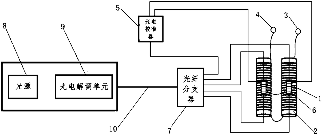
[0021] The invention discloses an optical current measuring device, which includes a sensing head system, a dynamic correction system, a photoelectric demodulation system and an optical fiber splitter 7;

[0022] The sensor head system includes a crystal light valve magnetic field sensor 1, a solenoid 2, P1 current terminal 3 and P2 current terminal 4, the crystal light valve magnetic field sensor 1 is fixed in the solenoid 2, and Set coaxially with the solenoid 2, the length of the crystal light valve magnetic field sensor 1 is shorter than the length of the solenoid 2, when the solenoid 2 is one, the P1 current terminal 3, P2 current terminal 4 is drawn from both ends of the solenoid 2, the P1 current terminal 3 and the P2 current terminal 4 are connected to the measured current, and the two ends of the crystal light valve magnetic field sensor 1 are connected to the downlink optical interface of the optical fiber splitter 7 through an optical fiber , the number of the cryst...

Embodiment 2

[0033] see figure 1 , the present invention discloses an optical current measuring device, including a sensing head system, a dynamic correction system, a photoelectric demodulation system and an optical fiber splitter 7;

[0034] The sensing head system includes two crystal light valve magnetic field sensors 1, two solenoids 2, P1 current terminal 3 and P2 current terminal 4, and the crystal light valve magnetic field sensor 1 is fixed in the solenoid 2 , and is arranged coaxially with the solenoid 2, the length of the crystal light valve magnetic field sensor 1 is less than the length of the solenoid 2, and when there are two solenoids 2, one of the solenoids 2 The first solenoid connected in sequence leads to P1 current terminal 3, and the last solenoid connected in sequence leads to P2 current terminal 4, and P1 current terminal 3 and P2 current terminal 4 are connected to the measured current. , both ends of the crystal light valve magnetic field sensor 1 are connected t...


PUM

PropertyMeasurementUnit
Wavelengthaaaaaaaaaa

Abstract

The invention discloses an optical current measurement device. The optical current measurement device comprises a sensing head system, a dynamic calibration system, a photoelectric demodulation systemand an optical fiber splitter, wherein the sensing head system comprises one or more crystal light valve magnetic field sensors, one or more solenoids, a P1 current terminal and a P2 current terminal, wherein the two ends of each crystal light valve magnetic field sensor are connected with the optical fiber splitter through optical fibers; the dynamic calibration system is connected with a downlink optical interface of the optical fiber splitter through an optical fiber; the photoelectric demodulation system comprises a light source, a photoelectric demodulation unit and an optical cable andis connected with the optical fiber splitter through the optical cable. According to the optical current measurement device, influence of factors such as temperature, magnetic field and the like is eliminated, a current signal is amplified once by the solenoids, meanwhile, by means of differential dual-optical-path detection, external magnetic field interference is eliminated, measurement precision of an optical transformer is greatly improved, the minimum rated current capable of being measured is 0.5 A, and the accuracy class is 0.2S level.

Description

technical field [0001] The invention relates to the technical field of electric equipment, in particular to an optical current measuring device. Background technique [0002] At present, oil-filled electromagnetic induction current transformers are widely used in power systems to measure current under high-voltage and ultra-high-voltage conditions. Magnetic saturation and many other shortcomings. Therefore, people have been trying to find a new type of current transformer. The optical current transformer based on the principle of Faraday's magneto-optic effect is considered to be a new type of current measuring device with wide application prospects. It has simple and reliable insulation, no magnetic saturation, No secondary open circuit danger, strong anti-electromagnetic interference ability, small size, light weight, convenient installation and transportation, etc. Compared with traditional CT, it has considerable cost performance. Therefore, at present, this field has ...

Claims


Application Information

Patent Timeline
IPC IPC(8): G01R15/24G01R19/00
CPCG01R15/24G01R19/0092
Inventor 刘英
Owner 江苏鑫航电力设备工程有限公司
Why Eureka
Try Eureka