Underground target recognition method based on joint inversion

A technology of target recognition and joint inversion, applied in the directions of acoustic re-radiation, electrical/magnetic exploration, geophysical measurement, etc., can solve the problems of inaccurate results, inability to converge, and very high requirements, and achieve the effect of small amount of calculation

Active Publication Date: 2018-11-13
INST OF ELECTRONICS CHINESE ACAD OF SCI
View PDF6 Cites 5 Cited by
  • Summary
  • Abstract
  • Description
  • Claims
  • Application Information

AI Technical Summary

Problems solved by technology

At present, the commonly used method is to use the measured response to give the approximate plane position of the underground target, but the buried depth, inclination angle and dipole intensity of the target cannot be obtained through the measured response, and only guessed initial values ​​can be given, while the generally used local optimal The LM algorithm has very high requirements on the initial value. If the initial value is inaccurate, the inversion result of the final solution will be quite different from the actual one.
However, it takes a long time to adopt the global optimization DE algorithm, and the global search and local search capabilities of the DE algorithm are contradictory, and there is also the problem of not being able to converge to the optimal solution
[0005] On the basis of the inversion results, the fitting expression of the dipole intensity is obtained, but the fitting process needs to be substituted into all the observation time points of the quadratic field response, including the late signal which is very sensitive to noise, which will cause large The amount of calculation, and may fit inaccurate results

Method used


Image

  • Underground target recognition method based on joint inversion
  • Underground target recognition method based on joint inversion
  • Underground target recognition method based on joint inversion

Examples


specific Embodiment

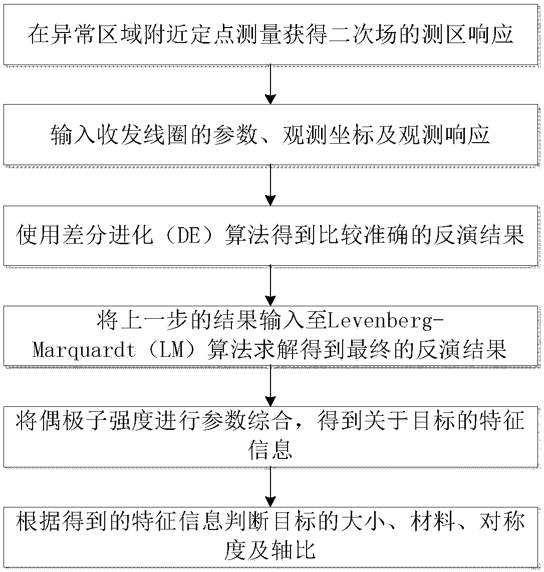
[0061] In this specific embodiment, the underground target is identified through the described method for identifying the underground target based on the joint inversion of DE-LM.

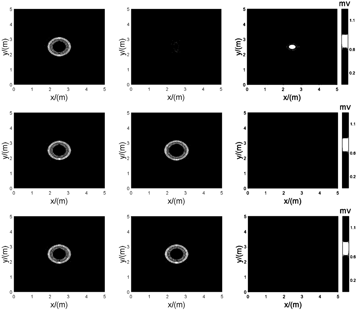
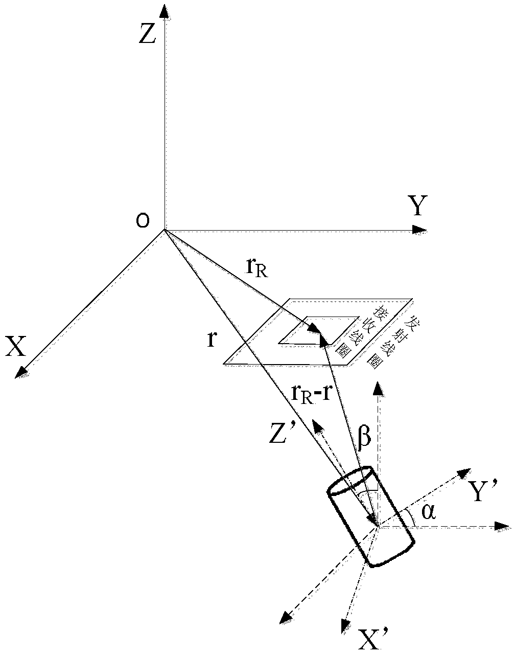
[0062] The measurement area is 5m*5m, and the observation coordinate system is established. A steel drum with a size of 20*10*10 (cm) is placed at the coordinates (2.5, 2.5, -1.5), and the α and β inclination angles are both 0°. The electromagnetic detection system measures the secondary field response of the target at a fixed point interval of 50cm, see figure 2 .

[0063] Input the parameters of the transmitting and receiving coil of the electromagnetic detection system, the square transmitting coil is 1m*1m, the transmitting current is 6A, and the square receiving coil is 0.5m*0.5m, placed concentrically and coplanarly with the transmitting coil.

[0064] When the time-domain electromagnetic method is used to invert underground targets, there are many parameters to be inverted, and the dipole ...


PUM


Abstract

The invention provides an underground target recognition method based on joint inversion. The underground target recognition method comprises a first step of establishing an observation coordinate system near an abnormal region, recording the coordinates of a transmitting coil and a receiving coil, and obtaining the measurement area response of a secondary field through fixed point measurement; asecond step of inputting parameters of the transmitting coil and the receiving coil of an electromagnetic detection system, observing coordinates and observing responses; a third step of carrying outprimary inversion by using a first optimization algorithm to obtain an inversion result; a fourth step of inputting the inversion result obtained in the third step into a second optimization algorithmfor solving, so as to obtain a final inversion result; a fifth step of carrying out information identification on a to-be-detected object according to the final inversion result obtained in the fourth step. In practical application, the method can be used for accurately inverting underground target information and judging the characteristics of a target.

Description

technical field [0001] The invention belongs to the technical field of underground target identification, in particular to an underground target identification method based on joint inversion. Background technique [0002] The time-domain electromagnetic method is a non-destructive detection method based on the principle of electromagnetic induction. It uses an ungrounded loop (magnetic source) or a grounded line source (electric couple source) to emit a primary field underground. , the induced eddy current excited in the underground conductor target will generate an induced electromagnetic field that varies with time. Due to the very low frequency of the transmitted signal, the time-domain electromagnetic method satisfies the diffusion equation of electromagnetic waves instead of the wave equation. Due to the volume effect of the diffusion field, its resolution is very low, so it is impossible to use the time-domain electromagnetic method to directly detect underground targ...

Claims


Application Information

Patent Timeline
Patent Type & Authority Applications(China)
IPC IPC(8): G01V3/10G01N23/00
CPCG01N23/00G01V3/10
Inventor 张晓娟谢吴鹏
Owner INST OF ELECTRONICS CHINESE ACAD OF SCI
Why Eureka
Try Eureka