Rubber frame, backlight module and display device

A backlight module and plastic frame technology, applied in projection devices, printing devices, optics, etc., can solve problems affecting screen-to-screen ratio, save occupied space, increase screen-to-body ratio, and reduce non-effective viewing areas area effect

Pending Publication Date: 2018-11-13
SHENZHEN SOUTH POLE OPTOELECTRONICS TECH
View PDF0 Cites 0 Cited by
  • Summary
  • Abstract
  • Description
  • Claims
  • Application Information

AI Technical Summary

Problems solved by technology

However, it is necessary to reserve the position of the front camera of the mobile phone, and the reserved position temporarily uses the screen display position, thereby affecting the screen ratio of the screen

Method used


Image

  • Rubber frame, backlight module and display device
  • Rubber frame, backlight module and display device
  • Rubber frame, backlight module and display device

Examples


Embodiment 1

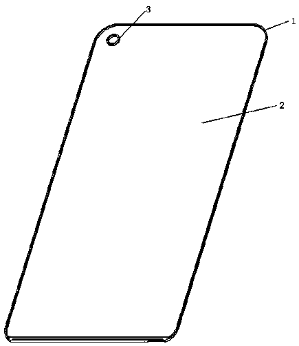
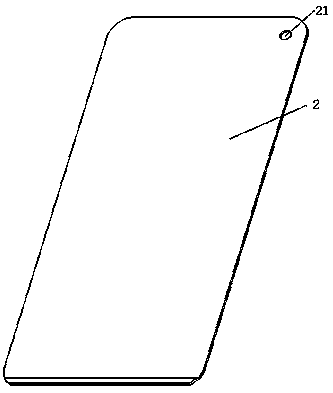
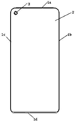
[0027] This embodiment provides a plastic frame, such as figure 1 and 2 As shown, the plastic frame includes a frame body 1 and a bottom plate 2 , the frame body 1 is arranged around the bottom plate 2 and forms an integral structure with the bottom plate 2 . The frame body 1 extends in a direction perpendicular to the bottom plate 2, and the bottom plate 2 is the bottom surface of the frame body 1, and the front of the frame body 1 is an opening for contact with the liquid crystal covering the frame body 1. The panel matches. The bottom plate 2 is provided with a positioning ring 3 along the extending direction of the frame body 1 , and the inner hole of the positioning ring 3 and the bottom plate 2 form a receiving space for accommodating the front camera. In this embodiment, the front camera is placed in the accommodation space formed by the inner hole of the positioning ring 3 and the bottom plate 2, which avoids reserving a groove on the top edge of the frame body 1, re...

Embodiment 2

[0036] This embodiment provides a backlight module, such as Figure 6-8 As shown, the backlight module includes a plastic frame 15, a light guide plate 8, and a backlight source 13; the light guide plate 8 is provided with a second through hole, and the aperture of the second through hole is the same as the outer diameter of the positioning ring 3. Matched with the diameter, the light guide plate is loaded in the plastic frame 15 and sleeved on the positioning ring 3 through the second through hole. The plastic frame 15 wraps the periphery of the light guide plate, and there is a gap between the bottom edge of the plastic frame 15 and the light guide plate, and the backlight source 13 is installed in the gap and connected to the light guide plate. 8 and the bottom edge are not in contact. In this embodiment, the plastic frame 15 adopts the plastic frame described in the above-mentioned embodiments, and details will not be described here.

[0037] Please continue to refer to ...

Embodiment 3

[0042] This embodiment provides a display device, which includes the backlight module described in the above embodiment, a front camera, and a liquid crystal panel mounted on the backlight module, and the front camera is assembled on the The positioning ring is used to accommodate the front camera through the positioning ring. Wherein, a display hole may be provided on the liquid crystal panel, and the front camera partially extends out of the positioning ring and is placed in the display hole, so that the front camera can take pictures through the display hole. image.


PUM


Abstract

The invention discloses a rubber frame, a backlight module and a display device. The rubber frame comprises a frame body and a base plate connected to bottom surface of the frame body, wherein a firstthrough hole is formed in the base plate, a positioning ring is arranged on the base plate, surrounds the first through hole and extends towards the front surface of the frame body, and an accommodating space for accommodating a camera is formed by the positioning ring and the first through hole. By arranging the front-mounted camera by virtue of the positioning ring, the situation that a groovefor the front-mounted camera is preserved in a house is avoided, the occupied space of the front-mounted camera is saved, and the area of a non-valid visual region is reduced, so that the screen-to-body ratio is increased.

Description

technical field [0001] The invention relates to the technical field of display devices, in particular to a plastic frame, a backlight module and a display device. Background technique [0002] With the rapid development of smart phone screens towards full screens, higher requirements are placed on manufacturers of backlight modules that provide illuminated displays under the screens. The backlight module is basically composed of rubber and iron integrated structure, LED, FPC flexible circuit board, light guide plate, reflector, optical film material, light-shielding adhesive, double-sided adhesive and other components. Conventional backlight modules increase the screen-to-body ratio by increasing the aspect ratio of the effective viewing area, designing a U-shaped groove on the top, and reducing the width of the side frame and bottom frame. Although the design of the opening structure on the top of the plastic iron and the removal of the U-shaped groove can reduce the scree...

Claims


Application Information

Patent Timeline
Patent Type & Authority Applications(China)
IPC IPC(8): G02F1/1333G02F1/13357G03B29/00
CPCG02F1/133308G02F1/133615G03B29/00
Inventor 徐贤强付迪飞姜发明
Owner SHENZHEN SOUTH POLE OPTOELECTRONICS TECH
Why Eureka
Try Eureka