Electrostatic releasing device of low-voltage triggering and high-maintenance voltage silicon-controlled rectifier

A high maintenance voltage, silicon rectifier technology, applied in the direction of electric solid devices, electrical components, semiconductor devices, etc., can solve the problems of low maintenance voltage, ineffective protection of internal circuits, device latch-up, etc. High, fast turn-on, the effect of increased emitter area

Active Publication Date: 2018-11-13
XIANGTAN UNIV
View PDF8 Cites 6 Cited by
  • Summary
  • Abstract
  • Description
  • Claims
  • Application Information

AI Technical Summary

Problems solved by technology

Therefore, a low-voltage trigger SCR is generated. The turn-on voltage of the device is the same as the breakdown voltage of the parasitic MOS, so the turn-on voltage can be well reduced, but the maintenance voltage is very low due to the characteristics of the latch-like feature during operation. This defect will make the internal The circuit is not effectively protected, and it is easy to cause device latch-up problems

Method used


Image

  • Electrostatic releasing device of low-voltage triggering and high-maintenance voltage silicon-controlled rectifier
  • Electrostatic releasing device of low-voltage triggering and high-maintenance voltage silicon-controlled rectifier
  • Electrostatic releasing device of low-voltage triggering and high-maintenance voltage silicon-controlled rectifier

Examples


Embodiment Construction

[0015] The present invention will be further described below in conjunction with the accompanying drawings and embodiments.

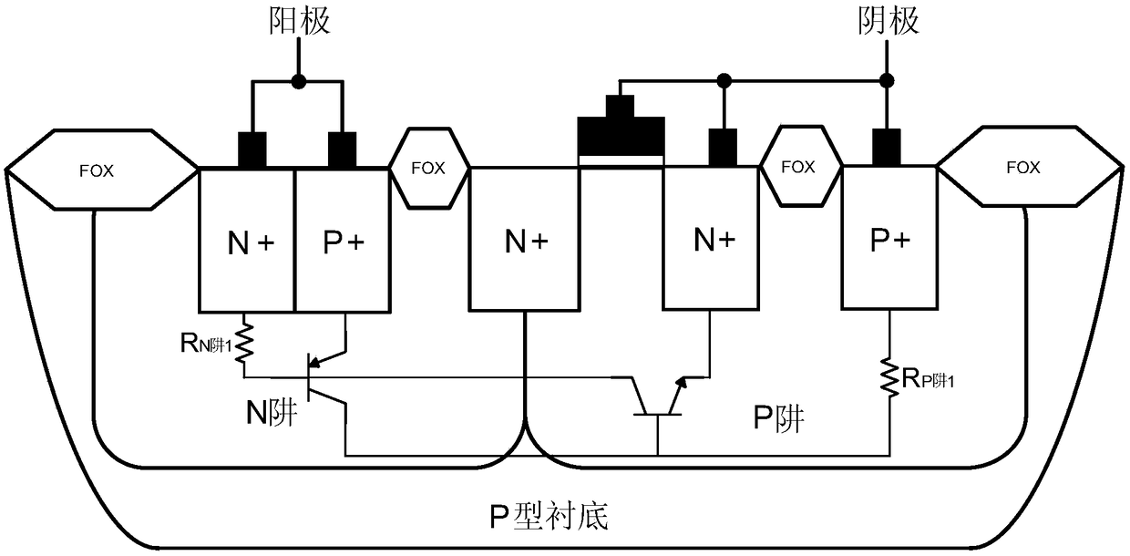
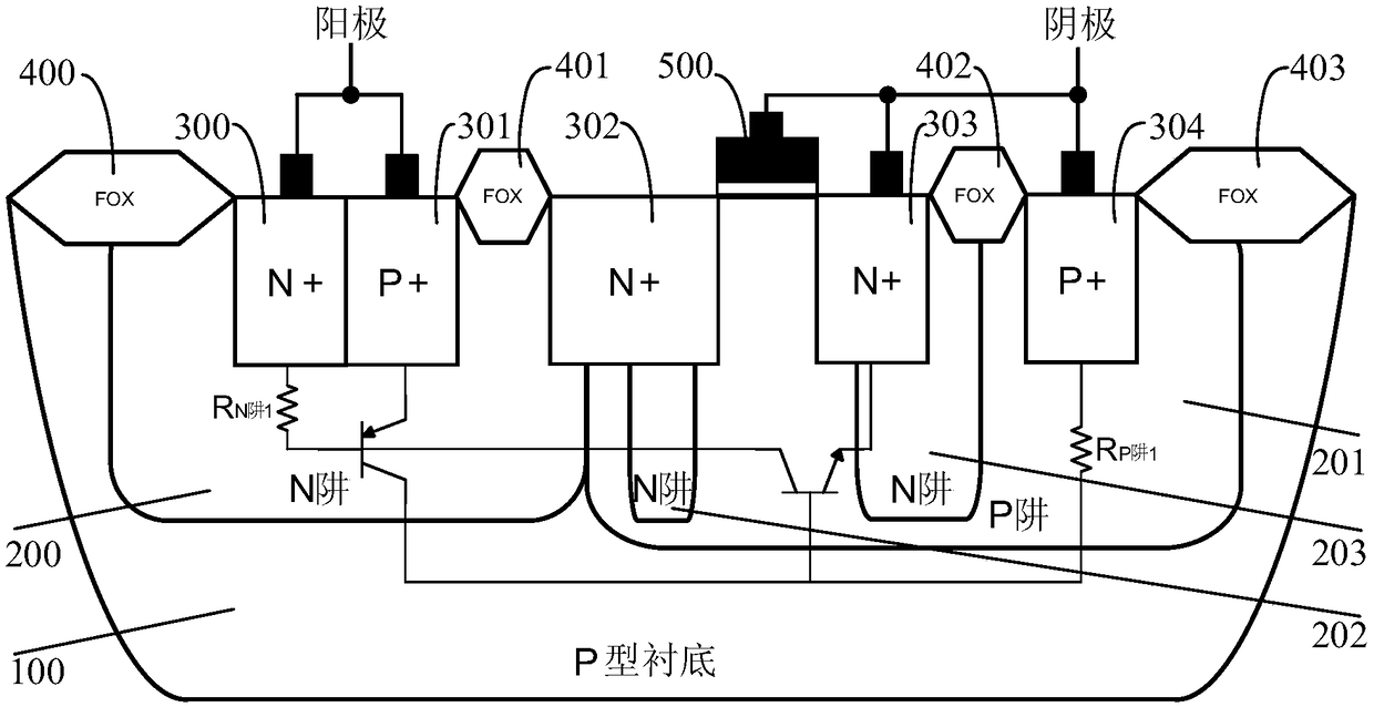
[0016] Such as image 3 As shown, a low-voltage trigger high sustain voltage silicon controlled rectifier electrostatic discharge device, including a P-type substrate 100; the P-type substrate 100 is provided with a first N well 200, a P well 201, and the first N well The right side of 200 is connected to the left side of P well 201; the first N+ implantation region 300 and the first P+ implantation region 301 are arranged in sequence from left to right in the first N well 200; A second N well 202, a third N+ implantation region 303, a third N well 203, and a second P+ implantation region 304 are arranged in sequence, wherein the third N+ implantation region 303 straddles the left side of the third N well 203 and the P well 201 A junction; a second N+ implantation region 302 is bridged between the first N well 200 and the P well 201, and the right side...


PUM


Abstract

The invention discloses an electrostatic releasing device of a low-voltage triggering and high-maintenance voltage silicon-controlled rectifier. The electrostatic releasing device comprises a P-type substrate, wherein a first N well and a P well are arranged in the P-type substrate, a first N+ injection region and a first P+ injection region are arranged in the first N well, a second N well, a third N+ injection region, a third N well and a second P+ injection region are arranged in the P well, a second N+ injection region bridges between the first N well and the P well, a poly-silicon gate isarranged between the second N+ injection region and the third N+ injection region, and the second N+ injection region, the poly-silicon gate and the third N+ injection region form a parasitic MOSFETfield-effect transistor structure. By adding the two N wells into the P well, the area of a parasitic NPN emitter is expanded to increase a failure current; and moreover, the current relief path can be extended after breakdown conduction of the device, the passing well resistance is increased, the device is more rapidly started, so that the maintenance voltage and the failure current of the deviceare increased, and the latch-up effect can be effectively prevented.

Description

technical field [0001] The invention relates to the field of electrostatic protection, in particular to an electrostatic discharge device for a low-voltage trigger high-maintaining voltage silicon-controlled rectifier. Background technique [0002] Electro-Static Discharge (ESD) is an inevitable phenomenon in the process of manufacturing, packaging, testing, transportation, assembly and use of integrated circuits. There are internal and external reasons for the generation of static discharge points. Static electricity accounts for 58% of the various reasons for the failure of integrated circuits, which poses a serious threat to the reliability of integrated circuits. There are two ways to protect integrated circuits from static electricity: one is to control and reduce the occurrence of static electricity and discharge, such as using electrostatic protective clothing, anti-static wrist straps, etc.; the other is to design static discharge devices around the chip to provide s...

Claims


Application Information

Patent Timeline
Patent Type & Authority Applications(China)
IPC IPC(8): H01L27/02
CPCH01L27/0262
Inventor 汪洋陈锡均周子杰
Owner XIANGTAN UNIV
Why Eureka
Try Eureka