Emergency power supply system of power plant

A technology of emergency power supply system and emergency power supply vehicle, which is applied in the field of electric power, can solve problems such as common mode faults, failure of nuclear power plants, damage to oil supply pipelines, and air pipelines, and achieve the goal of improving disaster resistance, redundancy, and reliability Effect

Inactive Publication Date: 2018-11-13
CHINA NUCLEAR POWER DESIGN COMPANY +3
View PDF4 Cites 3 Cited by
  • Summary
  • Abstract
  • Description
  • Claims
  • Application Information

AI Technical Summary

Problems solved by technology

However, this emergency power supply system has the following disadvantages: 1) The additional diesel generator capacity of the plant site is shared by the plant site, which cannot meet the requirements of power failure accidents for multiple units at the same site; 2) When floods, tsunamis, debris flows, etc. The electrical system of the engine may fail due to flooding, and the oil supply pipeline and air pipeline may be damaged due to external shocks. The cooling power of the fuel pool will lead to disastrous consequences for nuclear power plants; 3) The emergency power supply is provided by diesel generator sets, and there may be a risk of common mode failure; 4) The emergency diesel engine is in a hot standby state for a long time under normal conditions, and the operation and maintenance costs High, resulting in a reduction in the economics of nuclear power plant construction and operation
But this emergency power supply system still has the following disadvantages: 1) the investment of adding a diesel generating set exceeds 1% of the total cost of nuclear power, resulting in a decline in the economics of nuclear power construction; 2) the newly added additional diesel engine is still a fixed diesel engine, Affected by the working conditions of flooding, emergency power supply may not be provided in some over-design basic accidents, and at the same time, there may be a risk of common mode failure

Method used


Image

  • Emergency power supply system of power plant
  • Emergency power supply system of power plant
  • Emergency power supply system of power plant

Examples


Embodiment 1

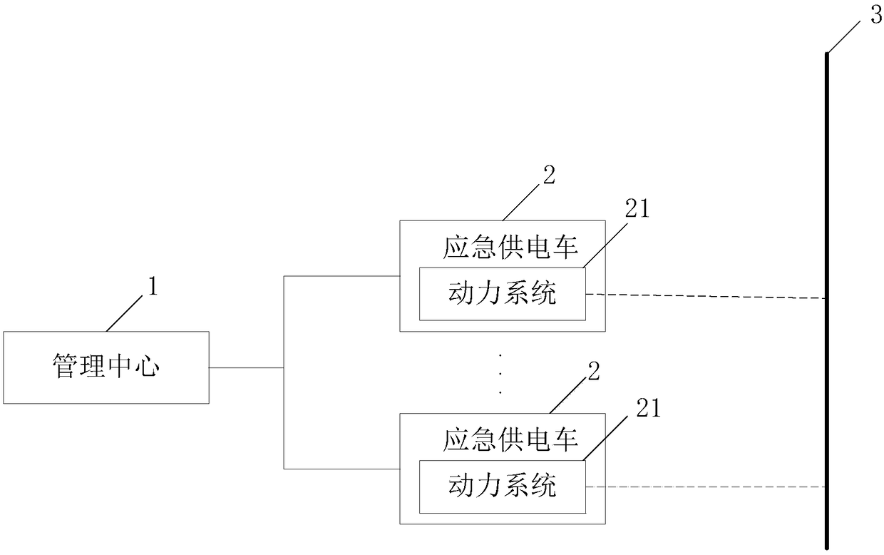
[0040] An embodiment of the present invention provides an emergency power supply system for a nuclear power plant, see figure 1 , the system consists of:

[0041] Management center 1 is used to send vehicle dispatching instructions when the plant power system and emergency generator stop supplying power;

[0042] At least one emergency power supply vehicle 2 is wirelessly connected to the management center 1, each of the emergency power supply vehicles 2 includes a power system 21, and each of the emergency power supply vehicles is used for when the vehicle dispatching instruction is not received, Drive the vehicle to work through the power system; when receiving the vehicle dispatching instruction, move to the interior of the nuclear power plant or thermal power plant according to the vehicle dispatching instruction, so that the power system is connected to the emergency bus of the nuclear power plant or thermal power plant to pass The power system supplies power to on-plant...


PUM


Abstract

The invention discloses an emergency power supply system of a power plant. The emergency power supply system comprises a management center and at least one emergency power supply vehicle, wherein themanagement center is used for sending a vehicle scheduling command when a plant electricity consumption system and an emergency generator stop power supply; the at least one emergency power supply vehicle is connected wirelessly with the management center; each emergency power supply vehicle comprises a power system and used for being driven by the power system to work when not receiving the vehicle scheduling command; when receiving the vehicle scheduling command, each emergency power supply vehicle moves into a nuclear power plant or a thermal power plant according to the vehicle schedulingcommand, and the power system is connected with an emergency busbar of the nuclear power plant or the thermal power plant, so that electricity can be supplied to the load in the plant through the power system. Reliability of an emergency power supply of the nuclear power plant and construction and operation economy of the nuclear power plant can be both taken into consideration.

Description

technical field [0001] The invention relates to the technical field of electric power, in particular to an emergency power supply system of a power plant. Background technique [0002] Nuclear power plants adopt the principle of defense in depth to provide multiple protections for the safety of nuclear power plants in terms of equipment and measures. The emergency power supply is an important protection equipment of the nuclear power plant. It together with the normal power supply system of the nuclear power plant constitutes the plant power system, which provides safe and reliable power supply for all the electrical equipment in the plant. The emergency power supply must provide power to the emergency safety equipment of the nuclear power plant to perform safety functions under normal operating conditions, during accident conditions or after accident conditions. [0003] An emergency power supply system in the prior art mainly includes a diesel generator and an additional ...

Claims


Application Information

Patent Timeline
Patent Type & Authority Applications(China)
IPC IPC(8): H02J9/08
CPCH02J9/08
Inventor 侯平利付月明林润黄美良
Owner CHINA NUCLEAR POWER DESIGN COMPANY
Why Eureka
Try Eureka