
Network alarm root analysis method and system, memory medium and computer equipment

An analysis method and root cause technology, applied in transmission systems, digital transmission systems, data exchange networks, etc., can solve problems such as being easily affected by cross-links, uncertainty in root cause analysis, etc., and achieve low-cost, intuitive and accurate analysis , enhance the effect of contact

Active Publication Date: 2018-11-13
北京思特奇信息技术股份有限公司
View PDF3 Cites 8 Cited by
  • Summary
  • Abstract
  • Description
  • Claims
  • Application Information

AI Technical Summary

Problems solved by technology

[0004] The existing alarm root cause analysis technology is mainly based on the topological relationship of network resources, directly through the alarm device information to find whether there is a parent or child node in the topology relationship, to determine whether the current alarm is a root cause alarm, or to reduce the dimensionality of the network topology relationship , decompose the network topology relationship into multiple links, and judge whether it is a root alarm by the position of the alarm instance in the link. The above technologies are based on some simple judgments of the network topology relationship. When the information has a certain degree of dispersion, it will cause uncertainty in the root cause analysis; especially at present, the alarm information of most monitoring systems relies on periodic information collection, and the alarm information with strong correlation may not be at exactly the same time The point reaches the monitoring system; and most of the methods of directly searching the network topology are only based on a layer of topological relationship, which is easily affected by cross-links

Method used


Image

  • Network alarm root analysis method and system, memory medium and computer equipment
  • Network alarm root analysis method and system, memory medium and computer equipment
  • Network alarm root analysis method and system, memory medium and computer equipment

Examples


Embodiment Construction

[0018] The principles and features of the present invention are described below in conjunction with the accompanying drawings, and the examples given are only used to explain the present invention, and are not intended to limit the scope of the present invention.

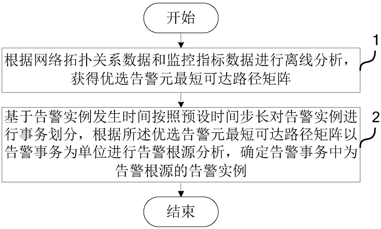
[0019] figure 1 A schematic flowchart of a network alarm root analysis method provided by an embodiment of the present invention is given. Such as figure 1 As shown, the root cause analysis method of the network alarm includes:

[0020] S1, perform offline analysis according to the network topology relationship data and monitoring index data, and obtain the shortest reachable path matrix of the optimal alarm element;

[0021] S2. Based on the occurrence time of the alarm instance, the alarm instance is divided into transactions according to the preset time step, and the root cause analysis of the alarm is performed in units of alarm transactions according to the optimal alarm element shortest reachable path matrix...


PUM


Abstract

The invention relates to a network alarm root analysis method and system. The method comprises the steps of carrying out offline analysis according to network topology relationship data and monitoringindex data, and obtaining an optimum alarm element shortest reachable path matrix; and carrying out transaction division on alarm instances based on alarm instance occurrence time according to a preset time step, carrying out alarm root analysis by taking alarm transaction as a unit according to the optimum alarm element shortest reachable path matrix, and determining the alarm instance as an alarm root in the alarm transaction. According to the method, the system, the memory medium and the computer equipment, through utilization of the network topology relationship data and the monitoring index data, topology data is converted into a topology matrix of alarm elements, analysis is carried out from a dimension of the alarm elements, and real-time alarm data is analyzed relatively visuallyand accurately. Clustering is carried out according to the alarm occurrence time, the alarm data is divided by taking the transaction as the unit, contact among alarms in the same time range is improved, and noisy point influence of data randomness and topology complexity resulting from carrying out topology searching according to the single alarm is reduced.

Description

technical field [0001] The invention relates to the technical field of computer applications, in particular to a method, system, medium and computer equipment for network alarm root analysis. Background technique [0002] With the continuous development of information technology and information scale, the scale of network applications is also expanding, and the scale of equipment supporting network applications is also increasing accordingly. Due to the huge and complex business volume, in daily operation and maintenance, the monitoring support system will generate a large number of alarms, and the personnel for operation and maintenance are limited. In order to ensure service quality and reduce operation and maintenance costs, a set of intelligent, high-accuracy The alarm root cause analysis solution helps operation and maintenance personnel to quickly locate problems and eliminate business system failures, ensuring the high-quality and stable operation of applications has ...

Claims


Application Information

Patent Timeline
IPC IPC(8): H04L12/24
CPCH04L41/0631H04L41/064H04L41/065
Inventor 谢远航
Owner 北京思特奇信息技术股份有限公司
Features
  • Generate Ideas
  • Intellectual Property
  • Life Sciences
  • Materials
  • Tech Scout
  • Unparalleled Data Quality
  • Higher Quality Content
  • 60% Fewer Hallucinations
Learn More