Factory floor cleaning equipment for metallurgy

A ground cleaning and equipment technology, applied in cleaning equipment, cleaning machinery, applications, etc., can solve the problems of long time consumption, large human resources, and low cleanliness of the ground.

Inactive Publication Date: 2018-11-16
朱茂祖
View PDF7 Cites 5 Cited by
  • Summary
  • Abstract
  • Description
  • Claims
  • Application Information

AI Technical Summary

Problems solved by technology

[0006] In order to overcome the shortcomings of the traditional manual cleaning method, which takes a long time, consumes a large amount of human resources, and cleans the ground less neatly, the technical problem to be solved is to provide a resource that can shorten the cleaning time and cost of the ground. Floor cleaning equipment for metallurgical factories that cleans the floor adequately

Method used


Image

  • Factory floor cleaning equipment for metallurgy
  • Factory floor cleaning equipment for metallurgy

Examples


Embodiment 1

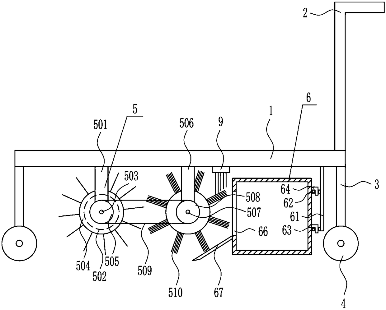
[0025] A metallurgical plant floor cleaning equipment, such as Figure 1-2 As shown, it includes a mounting plate 1, a push handle 2, a first pole 3, a traveling wheel 4, a cleaning mechanism 5 and a collection mechanism 6, the right side of the top of the mounting plate 1 is provided with a push handle 2, and the bottom of the mounting plate 1 is provided with a second A rod 3, the bottom of the first pole 3 is provided with a traveling wheel 4, a cleaning mechanism 5 is installed in the middle of the bottom of the mounting plate 1, and a collecting mechanism 6 is installed on the right side of the bottom of the mounting plate 1.

Embodiment 2

[0027] A metallurgical plant floor cleaning equipment, such as Figure 1-2 As shown, it includes a mounting plate 1, a push handle 2, a first pole 3, a traveling wheel 4, a cleaning mechanism 5 and a collection mechanism 6, the right side of the top of the mounting plate 1 is provided with a push handle 2, and the bottom of the mounting plate 1 is provided with a second A rod 3, the bottom of the first pole 3 is provided with a traveling wheel 4, a cleaning mechanism 5 is installed in the middle of the bottom of the mounting plate 1, and a collecting mechanism 6 is installed on the right side of the bottom of the mounting plate 1.

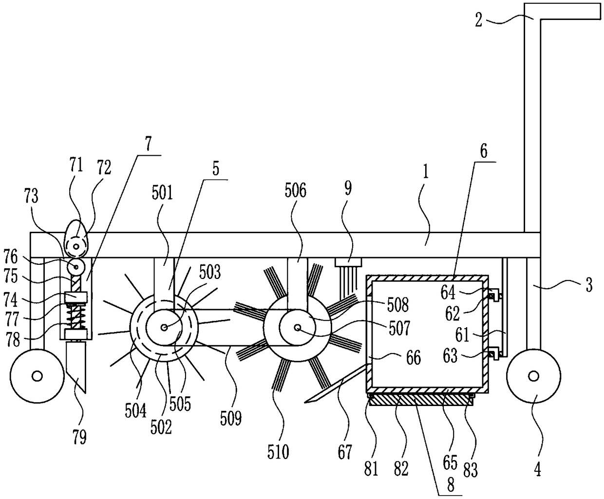
[0028]The cleaning mechanism 5 includes a second pole 501, a first motor 502, a first rotating shaft 503, a first roller brush 504, a first pulley 505, a third pole 506, a second rotating shaft 507, a second pulley 508, Flat belt 509 and cleaning roller brush 510, the middle left position of mounting plate 1 bottom is vertically connected with seco...

Embodiment 3

[0030] A metallurgical plant floor cleaning equipment, such as Figure 1-2 As shown, it includes a mounting plate 1, a push handle 2, a first pole 3, a traveling wheel 4, a cleaning mechanism 5 and a collection mechanism 6, the right side of the top of the mounting plate 1 is provided with a push handle 2, and the bottom of the mounting plate 1 is provided with a second A rod 3, the bottom of the first pole 3 is provided with a traveling wheel 4, a cleaning mechanism 5 is installed in the middle of the bottom of the mounting plate 1, and a collecting mechanism 6 is installed on the right side of the bottom of the mounting plate 1.

[0031] The cleaning mechanism 5 includes a second pole 501, a first motor 502, a first rotating shaft 503, a first roller brush 504, a first pulley 505, a third pole 506, a second rotating shaft 507, a second pulley 508, Flat belt 509 and cleaning roller brush 510, the middle left position of mounting plate 1 bottom is vertically connected with sec...


PUM


Abstract

The invention relates to cleaning equipment, in particular to factory floor cleaning equipment for metallurgy. The technical purpose is to provide the factory floor cleaning equipment for metallurgy capable of shortening the floor cleaning time, consuming fewer resources, and fully cleaning the floor. According to the technical scheme, the factory floor cleaning equipment for metallurgy comprisesan installing plate and the like; a pushing handle is arranged on the right side of the top of the installing plate, a first supporting rod is arranged at the bottom of the installing plate, walking wheels are arranged at the bottom of the first supporting rod, a cleaning mechanism is installed in the middle of the bottom of the installing plate, and a collecting mechanism is installed on the right side of the bottom of the installing plate. An operator operates the pushing handle to drive the equipment to run on the floor of a metallurgy factory, the cleaning mechanism and the collecting mechanism are utilized to clean the ground, and by utilizing the optimization of a knocking mechanism and an adsorption mechanism, the effects of shortening the floor cleaning time, consuming fewer resources, and fully cleaning the floor are achieved.

Description

technical field [0001] The invention relates to a cleaning device, in particular to a metallurgical factory floor cleaning device. Background technique [0002] Metallurgy is the process and technology of extracting metals or metal compounds from minerals, and using various processing methods to make metals into metal materials with certain properties. [0003] Metallurgy has a long history of development, from the Stone Age to the subsequent Bronze Age, to the large-scale development of modern iron and steel smelting. The history of human development incorporates the history of metallurgy. [0004] Metallurgical technologies mainly include pyrometallurgy, hydrometallurgy and electrometallurgy. With the successful application of physical chemistry in metallurgy, metallurgy has moved from technology to science, so there is a metallurgical engineering major in universities. [0005] During the production process of the metallurgical factory, a certain amount of impurities w...

Claims


Application Information

Patent Timeline
Patent Type & Authority Applications(China)
IPC IPC(8): A47L11/24A47L11/40
CPCA47L11/24A47L11/4013A47L11/4041A47L11/4069
Inventor 朱茂祖
Owner 朱茂祖
Why Eureka
Try Eureka