A multi-functional wide-flow high-efficiency gas-liquid separation device combining gravity and centrifugal technology

A gas-liquid separation device and combined technology, used in separation methods, dispersed particle separation, chemical instruments and methods, etc.

Active Publication Date: 2021-05-14
HARBIN ENG UNIV
View PDF19 Cites 0 Cited by
  • Summary
  • Abstract
  • Description
  • Claims
  • Application Information

AI Technical Summary

Problems solved by technology

However, the existing separation equipment cannot effectively solve the above problems

Method used


Image

  • A multi-functional wide-flow high-efficiency gas-liquid separation device combining gravity and centrifugal technology
  • A multi-functional wide-flow high-efficiency gas-liquid separation device combining gravity and centrifugal technology
  • A multi-functional wide-flow high-efficiency gas-liquid separation device combining gravity and centrifugal technology

Examples


Embodiment Construction

[0026] The present invention is described in more detail below in conjunction with accompanying drawing example:

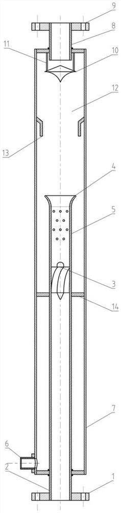
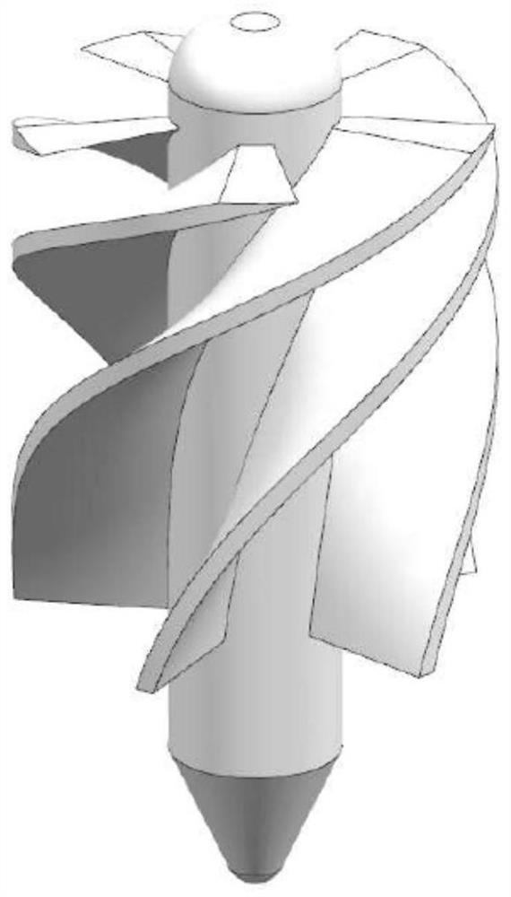
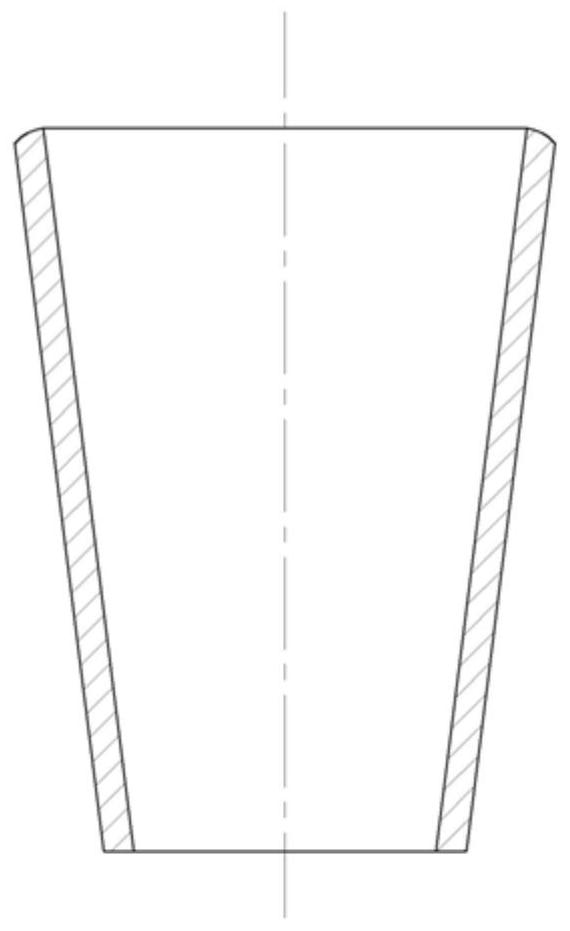
[0027] combine Figure 1-4 , the present invention is a multi-functional, wide-flow and high-efficiency gas-liquid separation device combining gravity and centrifugal technology. The main part is a sleeve structure, including a core tube 2 and a casing 7. The impeller 3 is installed inside the core tube 2; the inlet end of the core tube 2 is located outside the casing 7 and connected to the inlet flange 1; a support structure 14 is provided between the core tube 2 and the casing 7; the outlet of the core tube 2 The end is located inside the casing 7, and is connected with the expansion section 4, and the core pipe 2 forms an annular descending space between the part inside the casing 7 and the casing 7; the wall surface of the core pipe 2 between the impeller 3 and the expansion section 4 A hole section 5 is provided on it, and the hole section 5 is located insid...


PUM


Abstract

The object of the present invention is to provide a multifunctional wide-flow high-efficiency gas-liquid separation device combining gravity and centrifugal technology, which includes a sleeve and a core tube. The inlet end of the core tube is located outside the sleeve tube, and the outlet end of the core tube extends into the To the inside of the sleeve, a support structure is set between the core tube and the sleeve, an impeller is installed in the core tube, a water retaining ring is set on the inner wall of the sleeve above the outlet end of the core tube, and a gas phase outlet is set at the upper end of the sleeve. The lower end is provided with a liquid phase outlet. The opening section of the present invention not only reduces the oscillation problem caused by the change of the gas-liquid two-phase flow pattern, but also enables the liquid phase to enter the annular descending space between the core tube and the casing as soon as possible, thereby improving the separation efficiency, preventing fatigue damage, and increasing the service life. The separation baffle can block the liquid droplets carried in the gas core and shunt them to the inner wall of the sleeve. The annular cavity formed by the water retaining ring and the inner wall of the sleeve can effectively prevent the liquid on the wall from rushing up too high and being carried by the gas. These structures The setting can effectively improve the separation efficiency.

Description

technical field [0001] The invention relates to a gas-liquid separation device. Background technique [0002] Gas-liquid two-phase flow widely exists in many fields such as power, nuclear energy, petroleum, chemical industry, etc. In order to meet the requirements of the process, ensure the safety of the system operation or improve the production efficiency, it is often necessary to separate the gas phase and the liquid phase. [0003] At present, the gas-liquid separator widely used in the industry is mainly based on the density difference between the gas phase and the liquid phase to achieve gravity separation or centrifugal force separation. For the gravity separator, although the structure of the equipment is relatively simple, the equipment size is large, the separation period is long, and the efficiency is low. When the gas flow rate is too high, it is easy to cause secondary carryover problems, so it is suitable for low flow rate conditions (“ Gravity separation devi...

Claims


Application Information

Patent Timeline
Patent Type & Authority Patents(China)
IPC IPC(8): B01D45/14B01D45/02
CPCB01D45/02B01D45/14
Inventor 范广铭阎昌琪王建军王刚徐浚修曾晓波
Owner HARBIN ENG UNIV
Why Eureka
Try Eureka