
Vibration spring-pulling mechanism

A technology of pulling springs and electric vibration, which is applied in the field of spring mattress manufacturing, can solve the problems of particularly serious impact on production, high cost of enterprise personnel, and backward working methods, so as to improve the level of production automation, reduce the intensity of work, and ensure that there is no joint Effect

Inactive Publication Date: 2019-01-25
CENTRAL SOUTH UNIVERSITY OF FORESTRY AND TECHNOLOGY
View PDF8 Cites 0 Cited by
  • Summary
  • Abstract
  • Description
  • Claims
  • Application Information

AI Technical Summary

Problems solved by technology

Outdated working methods and low production efficiency
This operation method has a particularly serious impact on production when the enterprise is producing on an assembly line
The labor intensity of workers is high, the working hours are long, and the cost of enterprise personnel is high

Method used


Image

  • Vibration spring-pulling mechanism
  • Vibration spring-pulling mechanism
  • Vibration spring-pulling mechanism

Examples


Embodiment Construction

[0024] Combine below Figure 1 to Figure 6 The embodiments of the present invention will be described in detail.

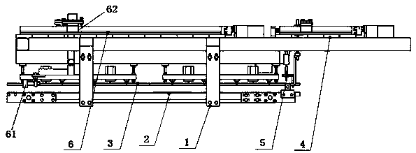
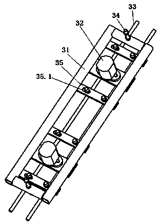
[0025] The vibration dialing spring mechanism includes a horizontally arranged bracket 1, which is characterized in that the said bracket 1 is equipped with a conveyor belt 2 for conveying the spring, an electric vibration mechanism 3 for dispersing the spring, and a single spring for pulling out a single spring. The spring mechanism 4 and the circlip mechanism 5 are used to prevent a single spring from being pulled out together with adjacent springs. The springs that are tightly pushed enter from the front end of the conveyor belt 2, and the electro-vibration mechanism 2 is arranged on the top of the conveyor belt 2 to transmit to the spring. Vertical vibration, the circlip mechanism 5 is arranged above the end of the conveyor belt 2, the spring mechanism 4 is located on the rear side of the circlip mechanism 5, the circlip mechanism 5 and the spring mechanism 4 ...


PUM


Abstract

A vibration spring-pulling mechanism includes a horizontally arranged bracket, a conveyor belt used for conveying springs is installed on the bracket, an electro-vibration mechanism for dispersing spring vibration, a spring-pulling mechanism for pulling out the springs one by one and a spring clamping mechanism for preventing one spring from being pulled out when the adjacent spring is pulled out.The tightly accumulated springs enters from the front end of the conveyor belt, the electro-vibration mechanism is arranged right above the conveyor belt and transmits vertical vibration ro the springs, the spring clamping mechanism is arranged on the upper portion of the tail end of the conveyor belt, the spring-pulling mechanism is located on the rear side of the spring clamping mechanism, thespring clamping mechanism and the spring-pulling mechanism vertically stretch into the springs, the spring-pulling mechanism horizontally moves so as to pull the springs one by one, and actions of theconveyor belt, the electro-vibration mechanism, the spring-pulling mechanism and the spring clamping mechanism are all controlled by a control system. The mechanism can effectively sort out the tightly accumulated springs one by one, the whole process does not need manual participation, the spring separation efficiency is high, the production automation level of a spring mattress is improved, theoperation intensity in the production process is reduced, and the production efficiency is improved.

Description

technical field [0001] The invention relates to a vibration pulling spring mechanism, which is used for pulling out the tightly pushed springs one by one, belonging to the field of spring mattress manufacturing. Background technique [0002] Compression springs are widely used in many industries today, and in most industries, especially in the production of spring mattresses, spring supply and installation operations are still manually sorted and then threaded. The operation method is backward and the production efficiency is low. In the case of enterprise assembly line production, this method of operation has a particularly serious impact on production. The labor intensity of workers is high, the working hours are long, and the cost of enterprise personnel is high. For improving the efficiency of enterprise spring sorting, reducing the work intensity of workers, saving resources and energy, the spring sorting mechanism has great application prospects. [0003] It is the ...

Claims


Application Information

Patent Timeline
Patent Type & Authority Applications(China)
IPC IPC(8): B65G47/34B65G47/82
CPCB65G47/34B65G47/82
Inventor 李立君刘涛喻秋良闵淑辉万斌
Owner CENTRAL SOUTH UNIVERSITY OF FORESTRY AND TECHNOLOGY
Learn More